RotoMetals2Titan ReloadingRepackboxInline Fabrication
Reloading EverythingLoad DataSnyders JerkyMidSouth Shooters Supply
Wideners Lee Precision

Thread: Making that Bullet Collator

  1. #5781
    Boolit Master TylerR's Avatar
    Join Date
    Dec 2008
    Posts
    2,013
    Quote Originally Posted by GWS View Post
    I agree that part is the best one to modify, but you still might end up with 2 or at most 3 different angle versions, which is better than 10. Good job.
    One size fits all!

  2. #5782
    Boolit Bub 45acp's Avatar
    Join Date
    Dec 2009
    Location
    Sweden
    Posts
    34
    Quote Originally Posted by TylerR View Post
    Make sure you align the bottom to build plate. looks like it is slightly off.
    Printed and tested.
    No jams yet after testing 200 bullets.
    Got it align now. I use some thicker screws causing plastic pushed out underneath on the previuos one.
    Thanks! Great work!
    More "natural" travel for the bullets now.
    Last edited by 45acp; 04-05-2022 at 01:32 AM.

  3. #5783
    Boolit Master GWS's Avatar
    Join Date
    May 2019
    Location
    New Mexico
    Posts
    1,369
    Looks like a winner......no problems on the bottom end of the spring either?

  4. #5784
    Boolit Bub 45acp's Avatar
    Join Date
    Dec 2009
    Location
    Sweden
    Posts
    34
    Nope, no problemo.
    Bullets drops sooo smooth now
    A winner for shure

  5. #5785
    Boolit Master TylerR's Avatar
    Join Date
    Dec 2008
    Posts
    2,013
    Quote Originally Posted by 45acp View Post
    Printed and tested.
    No jams yet after testing 200 bullets.
    Got it align now. I use some thicker screws causing plastic pushed out underneath on the previuos one.
    Thanks! Great work!
    More "natural" travel for the bullets now.
    Excellent! I did print one myself. Have not had a chance to try it. Although I am not having the same issue.

  6. #5786
    Boolit Buddy
    Join Date
    Sep 2011
    Posts
    145
    Quote Originally Posted by TylerR View Post
    my opinion is that Mongo is a bit overkill. 300mm is perfect for cases or bullets, which is why I named it Just Right. And yes, AM's used 147.5mm plates. You can still create those with the generator, but they are not part of my project. The "original" collator I designed uses 179.5 plates.
    Thanks,

    I ended up finding a barely used CR10V3, which has a direct drive extruder, for $350 Canadian ($300USD) and he threw in 2 spools of brand new filament.

    I’m in the process of adding Auto Bed Levelling and fixing a couple of minor extruder issues.
    Hopefully by tonight or tomorrow it will be ready to start my first 300mm base.

  7. #5787
    Boolit Mold
    Join Date
    Apr 2018
    Posts
    17
    Quote Originally Posted by thump_rrr View Post
    Thanks,

    I ended up finding a barely used CR10V3, which has a direct drive extruder, for $350 Canadian ($300USD) and he threw in 2 spools of brand new filament.

    I’m in the process of adding Auto Bed Levelling and fixing a couple of minor extruder issues.
    Hopefully by tonight or tomorrow it will be ready to start my first 300mm base.

    Nic's firmware is a excellent choice for that machine if it still has the stock board and a BLT. It can be found on the faceballs its like nics creality firmware. Enjoy the v3 its a nice machine.

  8. #5788
    Boolit Buddy
    Join Date
    Sep 2011
    Posts
    145
    Quote Originally Posted by shibbykins View Post
    Nic's firmware is a excellent choice for that machine if it still has the stock board and a BLT. It can be found on the faceballs its like nics creality firmware. Enjoy the v3 its a nice machine.
    Thanks,
    Mine has the 8 bit 2.5.2 board
    I downloaded it this morning
    I’m assuming that it will work the same with either the BL Touch or CR Touch.

  9. #5789
    Boolit Buddy
    ranger391xt's Avatar
    Join Date
    Feb 2016
    Location
    Indiana
    Posts
    178
    Quote Originally Posted by ranger391xt View Post
    I've been working on designing a PCB (circuit board) that the relay could be soldered onto along with terminal blocks for the connection to the switch, Power supply, motor control, sensor and motor. My thinking is this would make connecting everything simpler and eliminate some of the need to solder wires together and reduce the rats nest in the box. It would also allow things like the sensor to be swapped out easily in the event of a component failure.

    I had layed it out based on the old schematic. Trying to determine if it is necessary to change it based on the new wiring diagram.

    looks like I could get 20 PCB printed in China pretty cheap. Not sure how long they would take to get here though. I may get a batch of them printed when I finalize things and offer a few of the extras here if there is interest.

    Here is what it might look like. Demension are approx 61mm X 47mm


    It has been awhile (2+ months...sheesh!), but I finally have something I can show. In mid-February the boards I ordered were printed and delivered. I then ordered the terminal blocks and relay from Amazon. First terminal blocks I ordered had pins that were bigger than the holes in the board and the pitch (pin spacing) was 5.08mm/0.2" instead of the 5mm spacing like the component I selected when designing the board. So those blocks went back and I found ones that would work and got them ordered. All this of course was at the same time the local PO was struggling with deliveries in my area due to carriers being out with Covid. Apparently they have to take a month off if they have it. Deliveries finally got back to normal near the end of February.

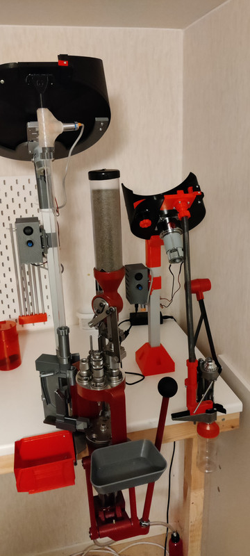
    After getting the boards, I decided to model a new box with built in standoffs/mounting posts for the relay board and speed controller I use. I also use different connectors for the prox switch, motor and power, so I added cutouts to work with those, and made it so the power came in the bottom of the box and the connectors for the prox switch and motor were on top. I also wanted to be able to mount it to the 3/4" black pipe I that my feeder mounts to, so included the mounts on the box.

    Click image for larger version. 

Name:	Electronics-Box.jpg 
Views:	32 
Size:	29.8 KB 
ID:	298708

    Now I have everything soldered to the board, the relay board and speed controller mounted in the box and connected and here is what it all looks like.

    Click image for larger version. 

Name:	20220406_222342.jpg 
Views:	67 
Size:	39.2 KB 
ID:	298709

    These are the connectors I use. I really don't care for those XT connectors for the motor, and trying to solder wire to JST sockets wasn't working for me.

    Click image for larger version. 

Name:	20220406_222443.jpg 
Views:	54 
Size:	50.3 KB 
ID:	298710

    This is the post mount/clamps I put on the box.

    Click image for larger version. 

Name:	20220406_222539.jpg 
Views:	43 
Size:	62.4 KB 
ID:	298711

    I connected it to my feeder and it worked as expected - plate spun when powered and when bullets were detected by the proximity switch it stopped. Need to load test it now just to make sure it doesn't overheat or anything like that.

    And for you guys that were talking about the demands of baseball, I can identify. Coached girls basketball and soccer for a number of years. Don't coach any more, but the past weeks we have logged a lot of miles for soccer, which now seems to be a year round sport. The girls I coached from 3rd grade through Jr. High are all graduating this year and its been fantastic to see how much success they have had but it is hard to believe how quickly the time has passed....

  10. #5790
    Boolit Master GWS's Avatar
    Join Date
    May 2019
    Location
    New Mexico
    Posts
    1,369
    It all looks great! You've gone to a lot of effort.....should give you years and years of good service. The best part of 3D printing, is being able to make dang near anything custom to suit us just right. I'm finally done with 5 of them.....happy as can be. Time to clean up my wife says and get serious about reloading again.

    My coaching days are long over......all those kids are grown up and married and have their own kids to coach. I'm happy to let them.....but lots of good memories.

  11. #5791
    Boolit Master TylerR's Avatar
    Join Date
    Dec 2008
    Posts
    2,013
    Quote Originally Posted by ranger391xt View Post
    These are the connectors I use. I really don't care for those XT connectors for the motor, and trying to solder wire to JST sockets wasn't working for me.

    Click image for larger version. 

Name:	20220406_222443.jpg 
Views:	54 
Size:	50.3 KB 
ID:	298710
    That looks very nice! Can you provide a link to the connectors you are using?

  12. #5792
    Boolit Mold
    Join Date
    Apr 2022
    Posts
    1
    New to the site and found this bullet feeder on GitHub. Used the parts generator and have all of the parts printed just need to figure out how it all goes together. Can someone direct me to assembly instructions? Thanks in advance.

  13. #5793
    Boolit Master TylerR's Avatar
    Join Date
    Dec 2008
    Posts
    2,013
    Quote Originally Posted by wwiley View Post
    New to the site and found this bullet feeder on GitHub. Used the parts generator and have all of the parts printed just need to figure out how it all goes together. Can someone direct me to assembly instructions? Thanks in advance.
    There are no assembly instructions. There are pictures and videos in the project that show it assembled and operating, and it is a very straight forward process to complete.

  14. #5794
    Boolit Bub wbbh's Avatar
    Join Date
    Dec 2020
    Location
    North Augusta, SC
    Posts
    54
    I'm working on a fastener application list, but I need some input for motors, other than the ETGZMP38 from Dayton. If there are other fasteners I missed, please let me know and I'll add them.

    This is what I have so far:

    Attachment 298733

    Text Version:

    Fastener Application Chart
    Brass Chute M2x8 N/A M2 4
    Brass Chute Adjuster M3-20 M3 N/A 1
    Clutch Hub 6x32x1" Pan Head 6-32 6-32 2 & 4 Nuts
    Dillon Mount 3/8"x1" 3/8" Nylock N/A 1
    Drop Hole Adapter M2-8 N/A M8 4
    Flipper M3-16 N/A M3 1
    Flipper Spring Retainer M3-8 N/A N/A 1
    Item Fastener Nut Washer Count
    Latch Mount M3-8 N/A M3 1
    Motor, 634JS
    Motor, ETGZMP38 N/A 10-32, Flanged 4
    Motor, FC555
    Motor, JGY370
    Post Mount 3/8"x2" Bolt 3/8" Nut 3/8" 1
    Post Mount Angle Adjuster Screw 1/4"-20 1/4"-20 N/A 1
    Ramp M3-16 N/A M3 1
    Square Post Angle Clamp 3/8"x2" Bolt 3/8" 3/8" 1
    Square Post Angle Clamp Adjuster 1/4"-20x21/2" 1/4"-20 1/4" 1
    Switch Board M3-20 M3 M3 4
    Attached Thumbnails Attached Thumbnails Screen Shot 2022-04-07 at 3.07.59 PM.png  
    Last edited by wbbh; 04-07-2022 at 03:16 PM.

  15. #5795
    Boolit Buddy
    ranger391xt's Avatar
    Join Date
    Feb 2016
    Location
    Indiana
    Posts
    178
    Quote Originally Posted by TylerR View Post
    That looks very nice! Can you provide a link to the connectors you are using?
    Sure thing. Here are the various items I used, for anyone that may be interested.

    2 pin

    https://www.amazon.com/XLX-100PCS-Co...ps%2C76&sr=8-3


    3 pin

    https://www.amazon.com/RGBZONE-20Pai...ps%2C98&sr=8-3

    Power Connectors

    https://www.amazon.com/Tegg-Connecto...s%2C109&sr=8-3

    Motor Controller

    https://www.amazon.com/uniquegoods-1...s%2C136&sr=8-9


    Sent from my SM-N981U using Tapatalk

  16. #5796
    Boolit Man
    Join Date
    Mar 2014
    Location
    Southern Mississippi
    Posts
    94
    has anyone updated the plate spreadsheet on drop list lately???

  17. #5797
    Boolit Master TylerR's Avatar
    Join Date
    Dec 2008
    Posts
    2,013
    Quote Originally Posted by wbbh View Post
    I'm working on a fastener application list, but I need some input for motors, other than the ETGZMP38 from Dayton. If there are other fasteners I missed, please let me know and I'll add them.

    This is what I have so far:

    Attachment 298733

    Text Version:

    Fastener Application Chart
    Brass Chute M2x8 N/A M2 4
    Brass Chute Adjuster M3-20 M3 N/A 1
    Clutch Hub 6x32x1" Pan Head 6-32 6-32 2 & 4 Nuts
    Dillon Mount 3/8"x1" 3/8" Nylock N/A 1
    Drop Hole Adapter M2-8 N/A M8 4
    Flipper M3-16 N/A M3 1
    Flipper Spring Retainer M3-8 N/A N/A 1
    Item Fastener Nut Washer Count
    Latch Mount M3-8 N/A M3 1
    Motor, 634JS
    Motor, ETGZMP38 N/A 10-32, Flanged 4
    Motor, FC555
    Motor, JGY370
    Post Mount 3/8"x2" Bolt 3/8" Nut 3/8" 1
    Post Mount Angle Adjuster Screw 1/4"-20 1/4"-20 N/A 1
    Ramp M3-16 N/A M3 1
    Square Post Angle Clamp 3/8"x2" Bolt 3/8" 3/8" 1
    Square Post Angle Clamp Adjuster 1/4"-20x21/2" 1/4"-20 1/4" 1
    Switch Board M3-20 M3 M3 4
    That is very cool. Honestly I would not even bother listing the jgy370 or the FC555 motors. I removed them as recommended motors from the manual. The 634JS motor is the way to go. I used m4x10mm for that motor.

  18. #5798
    Boolit Man
    Join Date
    Mar 2014
    Location
    Southern Mississippi
    Posts
    94
    Quote Originally Posted by wbbh View Post
    I'm working on a fastener application list, but I need some input for motors, other than the ETGZMP38 from Dayton. If there are other fasteners I missed, please let me know and I'll add them.

    This is what I have so far:

    Attachment 298733

    Text Version:

    Fastener Application Chart
    Brass Chute M2x8 N/A M2 4
    Brass Chute Adjuster M3-20 M3 N/A 1
    Clutch Hub 6x32x1" Pan Head 6-32 6-32 2 & 4 Nuts
    Dillon Mount 3/8"x1" 3/8" Nylock N/A 1
    Drop Hole Adapter M2-8 N/A M8 4
    Flipper M3-16 N/A M3 1
    Flipper Spring Retainer M3-8 N/A N/A 1
    Item Fastener Nut Washer Count
    Latch Mount M3-8 N/A M3 1
    Motor, 634JS
    Motor, ETGZMP38 N/A 10-32, Flanged 4
    Motor, FC555
    Motor, JGY370
    Post Mount 3/8"x2" Bolt 3/8" Nut 3/8" 1
    Post Mount Angle Adjuster Screw 1/4"-20 1/4"-20 N/A 1
    Ramp M3-16 N/A M3 1
    Square Post Angle Clamp 3/8"x2" Bolt 3/8" 3/8" 1
    Square Post Angle Clamp Adjuster 1/4"-20x21/2" 1/4"-20 1/4" 1
    Switch Board M3-20 M3 M3 4
    The JGY motor uses M3x8 pan head screws... qty 4

    I was told that the hex clutch uses #6-32 x 1/2 inch screws and nylock nuts
    When i tried to use an M3-20 for the adjustable slide plate to hold the slide in place it is way too short... i think it need at least a 25mm length screw.

  19. #5799
    Boolit Master TylerR's Avatar
    Join Date
    Dec 2008
    Posts
    2,013
    Quote Originally Posted by azlester View Post
    has anyone updated the plate spreadsheet on drop list lately???
    That has not been updated in a long time.

  20. #5800
    Boolit Mold
    Join Date
    Jan 2022
    Posts
    21
    Quote Originally Posted by 45acp View Post
    This is my setup.
    Works pretty well
    That's what I am after. I have a 12" length of 1" square aluminum tube that looks like yours. I don't recall seeing that square base for the tube anywhere. Is that your own? Also, will 12" length be enough?

Posting Permissions

  • You may not post new threads
  • You may not post replies
  • You may not post attachments
  • You may not edit your posts
  •  
Abbreviations used in Reloading

BP Bronze Point IMR Improved Military Rifle PTD Pointed
BR Bench Rest M Magnum RN Round Nose
BT Boat Tail PL Power-Lokt SP Soft Point
C Compressed Charge PR Primer SPCL Soft Point "Core-Lokt"
HP Hollow Point PSPCL Pointed Soft Point "Core Lokt" C.O.L. Cartridge Overall Length
PSP Pointed Soft Point Spz Spitzer Point SBT Spitzer Boat Tail
LRN Lead Round Nose LWC Lead Wad Cutter LSWC Lead Semi Wad Cutter
GC Gas Check