I have gleaned much good info from the “Cast Boolits” forum, so I thought it would be a good idea to give back a little something.
I recently set about the task of expanding a Lyman boolit mould, as from stock it was dropping boolits a little small for my .3585 Star Lubesizer die (made by Chris, AKA Lathesmith).
I gathered as much info as I could on the subject, taking note of various tips, do’s and don’ts etc. After which, I decided on a plan but using my own methodology. I believe that I may have come up with a surprisingly better way of doing things, which makes some of the usual steps obsolete, and also expedites the process, whilst keeping it extremely accurate. This method will also not only help prevent making out of round cavities, but it makes it virtually impossible if you follow the instructions. It will also save you time, as you don’t need to do multiple clean ups and castings to check progress.
It may not have the same ring as “Beagling” a mould (I love that name), but I called it “Weeting”, seeing as my name is Weet…. Yeah okay, shameless plug LOL, but a guy has to have his fifteen minutes of fame sometime!
Okay, lets get to work.
The mould is a Lyman 4 Cavity 358429 4C Mould 38/357 170 Grains Pistol Bullet Mould (steel)
Using a typical alloy of Lead/WW mix, which I am not quite sure of the percentage, but puts out nice boolits which are of a decent hardness when given a water drop; are anywhere from .3565 to .3585 Which means that some, most in fact, pass through the Star lubesizer die with nothing more than gravity. This meant the lube was being squished everywhere, and the boolits were of inconsistent size.
I decided that the boolits would be better if they were coming from the mould at or around .360 which would allow for discrepancies and would size nicely to .3585
Step 1.
Cast a handful of boolits from the mould you are going to lap out, and take note of which cavity the boolits come from ie drop them onto a soft towel and keep them separated so you know which pile comes from which cavity. Caution, don’t drop them until they have set well, as you don’t want measurements taken from boolits that have deformed on impact. When they, and the mould have cooled, measure each boolit and take a note (the base/driving bands being the important measurement here). There will be some discrepancies, but you will be able to take an average for each set (ie four cavities in my mould), and in this way you can see if any particular cavity may need more/less work).
Note: As a matter of interest, nearly all boolits will show a little out of round, depending how they are measured. If you gently spin the boolit whilst holding it between the micrometres anvils, you will see that the values are usually most polar when taken in line with the faint mould line, then again at 90 degrees to this. It is the average of the smaller of the measurements which we should use as our reference.
So for example we might have:
Boolit cast from cavity 1. .357 (take an average measurement from three or four boolits from each cavity)
Boolit cast from cavity 2. .358
Boolit cast from cavity 3. .3585
Boolit cast from cavity 4. .358
Step 2.
Presuming all cavities are approximately the same, we can use one slug lap to work through all the cavities. If however one or more of the cavities differ considerably, then a slug will have to be used for each one individually. The goal however is to make them all consistent to each other. So, say if you found you had one which was very small in comparison, then just work on this one until it is ‘up’ with the others, then revert to using one slug lap for all.
In my mould, I found that one cavity was dropping about .001” smaller than the other three (see above), so that’s the one I worked on first, just to get it to the same as the others..
Okay, so lets work that small cavity out ...
Remove the mould handles and sprue plate, as this makes it all easier.
Take one of the boolits cast from the small cavity, and place it back into the small cavity. Close the two mould halves and place them in a vice, boolit base up (use soft jaws so you don’t mar the mould), and tighten the vice with reasonable force.
Take a metal dot punch with a nice wide 60 degree point and tap it gently a few times into the centre of the base of the boolit. This step is important for three reasons.
Firstly, it will swell the base outwards, making it a tight fit into the mould, taking out the minute amount of shrinkage when it was cast. This makes for a perfect fit, and as such you will get a perfect measurement of the cavities actual diameter using this swaged slug.
Secondly, it will stop the boolit from spinning in the cavity when you drill it (next step).
Thirdly, it obviously lets you get a centre on the base for the drill, also stops any chance of drill spinoff and mould damage.
So take out the boolit you have swaged (your reference gauge plug) and measure it, write down the result. This will give you a reference for the lapping procedure, and eliminate any guesswork. You can either replace the boolit and give it another light tap to “set” it again, else just swage another for drilling, and discard the first.
The point being here, that by simply swaging a slug at any point in the lapping process, will give you an exact measure of the increase of the CAVITY size when compared to your reference plug gauge.
Obviously, there is some shrinkage of cast boolits from the actual mould, and if you have measured firstly a slug cast (noting the alloy and casting temps etc), then you measure the ACTUAL cavity diameter from a swaged slug, you will have the actual shrinkage amount.
But in a practical sense, as long as you have an accurate measure of the actual cavity size (using your reference plug gauge), and presumably you know how much larger you need the diameter of your cast boolits to drop out, it is simply a matter of math.
For example, if the reference plug gauge measures .360 (that is not what a cast boolit would come out at remember), and you know that your boolits are actually dropping .0025” smaller than you would like, then you know that you must make the cavity measure .3625” ….. simple! NO GUESSWORK and no having to constantly keep cleaning and re-trying the mould by casting…Phew!
You can see here that there is a dark line (a small gap) between the cast boolit and the mould.
Here following the dot punch, you can see that the gap has been completely eliminated and the base is fully forced out to exact diameter of the cavity. You have now created a plug gauge by which you can measure the actual size of this cavity.
Note:
If you need to enlarge the base bands substantially, or you have a long boolit (rifle maybe), it might not be enough to just swage the base out with a dot punch. Follow this up by making a tapered hole (you will obviously need a taper reamer to follow the drilling operation) to a good depth in the boolit, and drift the appropriate taper pin into it. In this way it will force out the sides evenly, as opposed to just the base. As for my example shown here, the dot punch worked quite well, and was sufficient to push out both driving bands on my Keith style boolit.
Another method for those of you who don’t have access to a taper setup, is to use a bright steel nail, of say 4”. Do the “dot punch” procedure, but then drill the base with a drill a few thou smaller than the nail diameter. Apply a wipe of oil to the nail point, then carefully drift the nail into the hole, obviously with the mould clamped firmly in the vice to prevent the two halves moving apart.
Note: It wouldn’t hurt to grind the sharp point off the nail first, as a safety precaution.
Then when the nail is wedged in, to remove it, grasp the head with a rag and make a few small circular motions, This will force the boolit walls outwards even more, and also make for easy removal of the nail. Finally, clean up the hole with a larger drill bit, and put in a suitable bolt (step 3).
Step 3.
We are now going to fit a BRASS bolt into the boolit, approx. two thirds deep. I say brass, as it wont hurt your steel mould if you cause them to come into contact somehow. Steel will be fine however, if you are careful.
Take the assembly across to the bench drill (a bench drill will keep the hole all squared up and prevent headaches later) and drill down about a third of the depth of the boolit. A good indicator here is to wind a little electricians insulation tape on the drill bit as a depth gauge… else set the depth gauge on the drill itself if you have one!
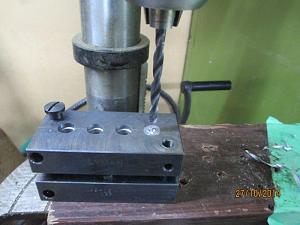
If you wish, use a small clamp to keep the mould pressed firmly together. I found that it didn’t need one, as long as you keep a grip on it, the swaged boolit wont spin. Don’t try and drill the hole in one pass, as the lead binds up on the drill bit. Clear it at least once or twice. It will stop things going pear shaped!
The hole diameter should be slightly smaller than the bolt, allowing you to push-thread the bolt into the soft lead alloy. It shouldn’t take much effort. It’s also much easier if you do this with the boolit still firmly held in the mould, and the complete assembly held in the vice. This will also help prevent distortion of your slug lap, or over expansion. You can also use an Engineers Square placed on the mould top, to check that you are going in square with the bolt. This is all bonus when you come to spin up the lap, and will make for an easier time.
You now have a lead ‘slug lap’ with a bolt attached, dead center and square on. The fancy looking bolt shown here was just something I found lying around.
Step 4.
Take a craft knife and gently trim off the front band (the bore riding band) of the slug lap. By using the bolt as a handle will help keep your fingers away from the blade, as it can jump out as it chops through the lead. I put it nose down on a cloth, and just snick small chips off a bit at a time. We are doing this (as in this instance) we don’t want to increase this diameter, we just want to increase the two base/driving bands.
Note. If you want to also increase the front band diameter, then obviously you don't need to remove any lead from the lap at all.
Now, here’s the clever part… take two medium/fine cut flat files, place one on the bench (remove the file handle so it sits flat), then the lap on top of the file, place the other file over the top, and then VERY lightly press and roll the slug lap between the two files keeping the pressure even and light. This does two things. It raises the profile of the slug lap (stippling or "knurling" is a common way to expand metal for fitting in oversized holes), and also creates lots of small pockets that will trap the lapping paste. It doesn’t matter if the files are the same cut, as I found that having one slightly finer than the other made for a great surface on the laps bands.
You might notice a split in the lap shown. I cut four lines through the lap with a jewellers saw, to allow it to expand, but found that this was neither necessary, but actually proved awkward, so please ignore it for the purpose of the exercise.
Lap ready to be stippled.
This is the lap after a couple of gentle rolls between the files. You can see that the bands (that we are wanting to increase in diameter) have taken on a nice stippling. Notice the roughly chopped off forward (bore riding) band. This is all you need do, it doesn’t need to look pretty! Even if you hack into the lap ahead of the chopped band, it doesn’t matter at all.
Next thing we do is add a little lapping paste. Now, depending on the amount of material you wish to remove, and the finish of the surface, will determine the grade of abrasive to be used. If you use a too fine grit, you can end up taking forever, but also, if you have even done any ‘finishing’, you will know that it can also lead to problems. Fine abrading or “polishing” when there is significant material to remove, is a no-no, as you will end up losing “crisp lines” or in the case of a cylindrical hole, you will wear it out of round etc. Toothpaste or Autosol (or any fine abrasive) is a final stage polish, and I wouldn’t recommended fine polish for increasing a cavity by any significant amount.
That said, neither are you looking to measure the increase with a steel rule, so the same caution goes for too coarse a grit.
I used some silicon carbide in a medium (medium stone tumbling grade) grit. I’m guessing it is about a 180 grit size (maybe finer). If you rub it between the fingers you cant really feel abrasion, but rubbed between two fingernails you can feel it bite. I sort of guesstimated it would be about right for the job, and it was. I made a paste of high temp grease, and grit, and applied it sparingly to the base bands. It adheres nicely, and we will later use light machine oil as a lubricant.
Next, put the lap into the cavity of one half of the mould and place the other half on top. You will notice that the mould will not close, and by a substantial amount. Don’t panic. This is because you have stippled the lap, and also added grit paste causing it to seem much too big in diameter. So, put the assembly onto the bench, and using the heel of your hand tap down the top half of the mould carefully a couple of times. This will squash the stippling down and help to “set” some grit into the soft lead lap. Open the mould and rotate the lap through 90 degrees, wiping off any squished out paste from the mould faces. Repeat the procedure over. It will take a few turns of the lap before you can get the mould nearly closed. When you have a gap of only a few thou, you are ready to start lapping.
This is about what plate gap you should see after rotating the lap and tapping the mould together a few times. The gap will close up gradually as the lapping action peens down the stippling on the lap, and also to some small degree removes material from the mould.
Place the mould on the edge of the bench, get a vari-speed battery drill (don’t use a big heavy one speed drill) with a suitable socket adaptor, and gently and slowly spin the bolt/lap in the mould. Keeping one hand on the top of the mould, using enough downwards pressure to just allow the lap to spin. Keep the drill square on to the mould and try not to tilt it or allow it to “rest” its weight downwards ie take the weight of the drill yourself. This is why a lightweight battery drill is best.
As you get used to the operation, you will be able to confidently increase the drill speed, knowing when to stop/check/lubricate & clean.
Notice, I haven’t yet placed my hand on top of the mould assembly, this was for clarity of the picture.
A freshly stippled and gritted lap is a bit bumpy on run-up, but only for a second or two, then it settles in. Don't be alarmed by the chatter or rough startup, as the soft lead alloy will take the beating, NOT the steel mold. The lead will quickly conform itself to the shape of the much harder steel. A soft lead lap does not work the same as would a hard wheel grinding tool for example.
After a few more seconds, open the two mould halves and take a look. Remove the slug lap and check that it is all okay. Before you pop it back in, carefully wipe any grinding paste from the faces of each mould half. Put a single droplet of light machine oil onto the lead slug when it is seated in one half of the mould, and close it up again. Give the slug a slow spin-up again with the drill, using hand pressure to keep the mould halves just pinching the slug lap.
... see part 2

|
   
   
|
|

 Reply With Quote