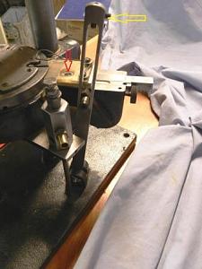
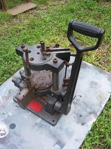
This is the most complex part of the whole machine as it controls both the primer seating and rotation of the shell plate. The octagonal column in the foreground is hooked up to a small air compressor set up to create a vacuum to help with the primer seating. The thing that is directly behind it rotates the shell plates and positions the primes to be seated. Not shown in the photo is the primer tube which would locate at the position indicated by the red arrow. The machine only came with one primer tube; I made a piece that would allow me to use the small and large primer tubes that I had on hand. The original had a brass piece that looked like the nipple from a percussion muzzleloader which screwed into a brass plate at the location of the red arrow. The primer tube was then placed over top of this brass nipple and the primers fed through it.
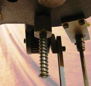
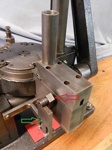
First I will explain how this rotates the shell plate. This like the case feeder uses a rack and pinion gearing system to operate, the gear teeth of the rack which are visible sticking out to the right of the assembly in photo 10. The motion of the gear is controlled by the long bar indicated also in photo 10 by the yellow arrow with the slot cut out for the lever arm. The Allen screws at the top are primer seating adjustments.
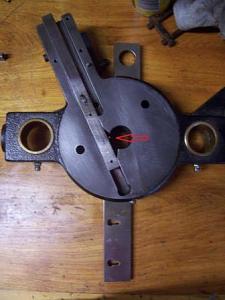
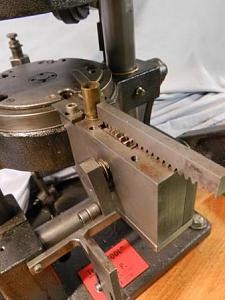
Photo 11 shows the ram plate removed from the press and the shell plate and its mounting system removed. The long bar that is in the slot cutout is the gear rack that rotates the shell plate show in the position at the end of the downward stroke. The arrow indicates the location of a ratchet tooth that engages the gear indicated below in photo 12 by the red arrow. This assembly is inserted through the bottom of the ram and is secured at the top by the nut on the right.
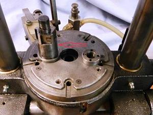 Photo 12
At the top of the press stroke the lever arm is forced from the 10 o�clock to the 6 o�clock position. This pushes the rack into the ram along the slot pushing the ratchet tooth over one of the gear teeth. On the downward stroke the rack is force back along the slot the ratchet tooth engages the gear teeth rotating the ratchet assembly, which in turn rotates the shell plate assembly.
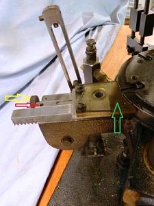
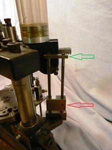
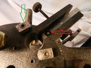
Photo 13 gives a better view of the priming mechanism. The bar that is being indicated by the red arrow is the priming arm. It is connected to the gear rack by a spring loaded ball bearing witch fits into a small indent on its side. The movement of the gear rack in the slot causes the ball bearing to engage the indent allowing the priming arm to travel with the gear rack. The adjustment wheel indicated by the orange arrow is the priming arm adjustment stop, moving it in or out allows for alignment between the hole in the priming arm and primer tube to be concentric. The Allen screws in the vertical bar with the slot cut out adjust the movement of the priming arm within the slot to allow for the priming arm hole and priming post to be aligned. The clear plastic guard piece indicated by the green arrow is to prevent anything from falling in front of the priming arm and hindering its forward travel. I do not know what function the wire that secured on top of the plate does. I have found out that if the gear rack is not properly secured in place by the plate the movement of the gear will cause the indexing gear rack to lift up and lock up the machine.
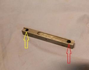 Photo 14
Photo 14 gives a better view of just the primer bar and the indent on the side that engages the spring loaded ball bearing in the gear rack. The two holes at each end had me confused until; I figured out that it allows it to be used for both large and small primers. By rotating the bar about the indent�s axis allows for the user to switch between large (red arrow) and small (yellow arrow) primers. The way that the bar is oriented in the photos shows that it is setup for using large primers. At the end of the bars forward travel at the top stoke of the press the primers are positioned on top of the primer ram. At the bottom stroke a bolt on the bottom of the base plate pushes up on the ram seating the fresh primer into the case. The photo 15 shows the priming ram on the underside of the presses ram.
After the primer has been seated the case is charged with powder on the upward stroke. The original system would have used a vertical bar like the priming system to engage a lever on the powder measure, similar to the old Hornady pro-jector system. I lucked out since my press had been retro fitted with a Dillon powder measure. From the powder measure the case rotates over to the bullet feeder and seating system show in photo 16.
Like everything else on this press this operates using a gear and rack system. As stated earlier the rotatory bullet magazine is made up of five tubes inside a protective tube two feet in length holding a little over 200 bullets. The red arrow indicates the adjustment for the feeding the bullets into the cases. The small horizontal bar at the top shown by the green arrow adjusts the bullet feeding rack forward and backward within its slot. This is to ensure that the bullets can drop straight down from the magazine into the hole cut out in the gear rack (I�ll show this later). The block with the slot cutout (red arrow) is the adjustment that moves the bullet to the seating position base on the height of the case; taller case would require it to be positioned higher on the vertical bars. As the ram comes up the lever on the gear comes into contact with the block starting the bullet feeder to move forward in the slot. As it travels higher the lever enters the slot in the block stopping its forward travel positioning a bullet into the case. As the ram travels back down the lever comes into contact with horizontal bar at the top force the gear rack back to its original position to receive a new bullet from the magazine. The entire system is adjustable from left to right to make sure that the gear rack comes to its finial position. When one of bullet tubes in the magazine is empty the outer protective tube is grasped and rotated to one of the other tubes loaded with bullets. The photo 17 shows the bullet feeder rack with in its slot with a 45 cal 200 gr semi wad-cutter in place indicated by the red arrow.
The knob that sticks out to the left of slot secures the bullet magazine into its position. Note the die station that the rack feeds into there are has no threads cut for the die to be screwed into. This is because this takes a special seating die that is held in place by the clamps one either side one is indicated by the green arrow. The photo 18 shows the seating die (different for each caliber) that is required by this machine.
The square slot cut out goes all the way though to allow for the bullet feeder rack to travel to the other side. The half circle cut out at the top is to account for the nose of the bullet in case it was taller than the bullet feeder rack. The circle at the bottom is to allow for the case to enter the die. Bullet seating adjustment is made in the typical manner with a seating plunger. When the bullet rack is in it farthest forward position within the slot the bullet in the rack and case should all be in line with each other.
After the bullet is seated in the case the shell plate is rotated into the next die station. I used this station for applying the crimp on the case mouth. From there the finished cartridge case would be pushed out of the shell plate by the case ejector on the lower stroke into a collection bin that would be held in place by two brackets on the front of the press. Mine did not have them when I bought it.
Overall I have found this to be a very nice machine to use I once I overcame the learning curve and have used it to load about 1600 rounds of 45 ACP so far, but it does have its drawbacks. For starters the weight of it makes it�s a pain to mount and remove from the bench top, if I had the space it would be permanently mounted. While this press is adapted to be used with both rifle and pistol cases I feel that it is best to set it up and leave it for one caliber. To switch calibers requires for the removal/ adjustment of the case feeder assembly and case ejector for the removal of the shell place and the adjustment of the cartridge guides. As well as the time needed to ensure that the primer and bullet feeding system are properly adjusted. Because the company is no longer in business spare parts are not easy to come by, I was lucky enough to find a person over on The High Road forum that had some extra shell plates that he was willing to part with. For the bullet feeding system requires changing the seating die, the bullet rack and, the bullet rotary magazine. I had no luck in find these parts during my online searches. So a quick order to McMaster Carr got me the required raw materials that I need to fabricate those three parts. I�ll admit that my fabricating skills are not the greatest but I was able to get my parts to work but probably not as well as the factory parts. I have also manually inserted bullets without any problems.
I hope that is helps any one that that finds one of these presses for the first time so that they won�t be as clueless as I was when I bought it.


 Reply With Quote