Alright, it's rather obvious y'all have no clue about heatsinking a part.
First. the wattage in the part has very little to do with much. that is the heat in the junction of the silicon.
Getting that heat out of the case and into the air is what you need to worry about.
For that you use the manufacturers tables for that device.
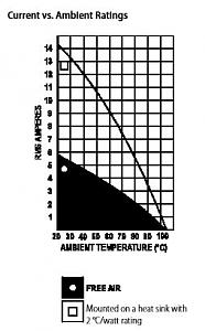
Above is a portion of the datasheet for a 25 amp SSR that is very much like what you would get from Auber Instruments.
The chart has 2 curves - lets work with the 'free air' one first - That is the black section.
Notice that Only at 20� C is the full current available as the device package gets warmer it will allow less and less current to flow before it burns up.
This is what you get if you don't have a heatsink. It is worse if you put the part inside a case and don't vent the box! The heat generated by the part causes the temp to raise - raising the temp farther.
You get a positive feedback loop - and things soon burn up.
Now look at the 2�C /Watt line. It's better at 20�C but it quickly degrades as the temp rises.
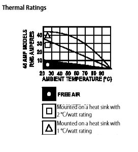
Here is what a given heatsink is capable of.
We have graphs for free air, 1�C/W, and 2�C/watt sinks. The �C/Watt is the amount a sink rises above ambient temp. The lower the number the better the sink.
Now a 12"x12"x1/8" (about 300 sq in) sheet of aluminum standing vertically in free air is approximately a 2�C/watt sink.
A 18" square (about 650 sq in ) x 1/8" thick sheet mounted the same way is a 1�C/watt sink.
I hope this helps.
In case any would like a complete spec sheet for a SSR of 'standard' design go
Here


 Reply With Quote


 .
.


