RepackboxRotoMetals2Titan ReloadingInline Fabrication
Reloading EverythingMidSouth Shooters SupplyLoad DataSnyders Jerky
Lee Precision Wideners
Results 1 to 9 of 9

Thread: Air feed for Star lubrisizer

  1. #1
    Boolit Master
    seagiant's Avatar
    Join Date
    May 2005
    Posts
    3,100

    Air feed for Star lubrisizer

    Hi,
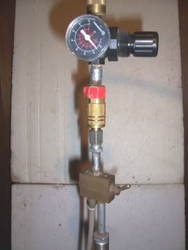
    I was going through some of the Archives and came across a thread where these guys that cast for a living thought very highly of the air pressure set up for their Stars. I have a lathe and from what I can see this shouldn't be that hard to make yourself.
    It looks like its just a cylinder about 1" in dia. and then that screws into the top of the lubrisizer. Is that all there is to it??? Any ideas or help with this would be appreciated. This looks like it might be a good home shop machinist project for my two Stars! Thanks!

  2. #2
    Boolit Buddy
    Join Date
    Apr 2005
    Location
    North Carolina
    Posts
    291
    that's all there is to it. also add a pressure guage, that allows you to adjust the pressure to it, a cheap one will be fine.

  3. #3
    Boolit Master
    seagiant's Avatar
    Join Date
    May 2005
    Posts
    3,100
    Hi John,
    I saw the schematic for this add on and it shows a washer that goes into the sizer in place of the spring assembly for pushing the lube. Can you tell me how that works? Thanks!

  4. #4
    Boolit Buddy
    Join Date
    Apr 2005
    Location
    North Carolina
    Posts
    291
    It's just a thick plastic bushing that is attached at the end of the rod with a bolt that threads into the inside of the push rod, as I remember it. I beleive there is a metal washer between the head of the bolt and the nylon or plastic bushing. I"m calling it a bushing but as I recall it's about 1/2" thick or so. Just need to make sure it's a tight fit of course but not so tight it can't push down.

  5. #5
    Boolit Master
    seagiant's Avatar
    Join Date
    May 2005
    Posts
    3,100
    Hi John,
    That's correct but here is what is causing me problems. If the threaded air nipple goes through the "bushing" and then a washer is put on and a bolt goes into the end of the nipple where does the air come into the luber at??? This is one of those things that actual observation would clear up in about 5 seconds but is confusing otherwise!Thanks!!!

  6. #6
    Boolit Master


    Springfield's Avatar
    Join Date
    May 2005
    Location
    San Jose, California
    Posts
    3,685
    Why don't you just take a look at Magmas site and see a real one, it might explan a lot. I plan on making my own as soon as I rebuild my lathe.

  7. #7
    Boolit Master
    seagiant's Avatar
    Join Date
    May 2005
    Posts
    3,100
    Hi,
    Like i mentioned in my original post I've done that already and still do not see exactly how it's set up. What's confussing(to me!) is that they have what looks like a bolt going into the end of the nipple to hold on a washer and bushing. So where does the air come in? Is there a hole drilled through lengthwise in the bolt to let the air pass???? If anyone owns one of these and can explain it I would appreciate it. I'm sure it's quite simple. Thanks!

  8. #8
    Boolit Master KYCaster's Avatar
    Join Date
    Mar 2005
    Location
    Rolling Fork River Valley
    Posts
    2,258
    Seagiant, let me see if I can explain this.
    Here's a pic of the air supply on my Star sizer.


    Now go to the Magma website and open the drawing for the Size Master air cylinder assembly.
    At the bottom of my pic is the air cylinder which corrosponds to Magma part no.LM061. It's a double acting air cylinder, 3/4in. bore X 4in. stroke. The toggle switch above that switches the cylinder from "UP" to "DOWN". Above that is the presssure regulator, adjustable from 0 to 150 psi. The air supply goes into the top of the regulator.
    The parts you need to make or alter are the reservoir cap, part no. LM025/LM026. You may be able to drill and tap the existing cap to accept the threads on the cylinder. You'll also need to make a part to replace or alter part no. LM40 so it will screw onto the end of the air cylinder ram and then fasten part no. LM45 onto your new LM40 with a new bolt, shorter than the original.
    You can get the cylinder, valve and regulator anyplace that has air/hydraulic parts. Around here its "The Parker Store". Everything else is standard pipe and tube fittings.
    Hope this helps. If you have any questions, just ask.

    Jerry
    edited to add correct link to pic
    Last edited by KYCaster; 02-04-2006 at 08:30 PM. Reason: add pic link

  9. #9
    Boolit Master KYCaster's Avatar
    Join Date
    Mar 2005
    Location
    Rolling Fork River Valley
    Posts
    2,258
    Well, that didn't work very well, did it?
    Look at the Test Photo thread in the Test Forum heading and you can see the pic. Don't know why it didn't show up here.

    Jerry
    I was able to add the right link to my earlier post so please disregard this post, just pretend it isn't here, OK?
    I think I'll go have an adult beverage or three and see if things get any better.
    Last edited by KYCaster; 02-04-2006 at 08:34 PM.

Posting Permissions

  • You may not post new threads
  • You may not post replies
  • You may not post attachments
  • You may not edit your posts
  •  
Abbreviations used in Reloading

BP Bronze Point IMR Improved Military Rifle PTD Pointed
BR Bench Rest M Magnum RN Round Nose
BT Boat Tail PL Power-Lokt SP Soft Point
C Compressed Charge PR Primer SPCL Soft Point "Core-Lokt"
HP Hollow Point PSPCL Pointed Soft Point "Core Lokt" C.O.L. Cartridge Overall Length
PSP Pointed Soft Point Spz Spitzer Point SBT Spitzer Boat Tail
LRN Lead Round Nose LWC Lead Wad Cutter LSWC Lead Semi Wad Cutter
GC Gas Check