What piping did you use to face mount it? I assume with a threaded flange?Originally Posted by Sig

Sent from my Pixel 5 using Tapatalk

|
   
   
|


|


What piping did you use to face mount it? I assume with a threaded flange?
Sent from my Pixel 5 using Tapatalk

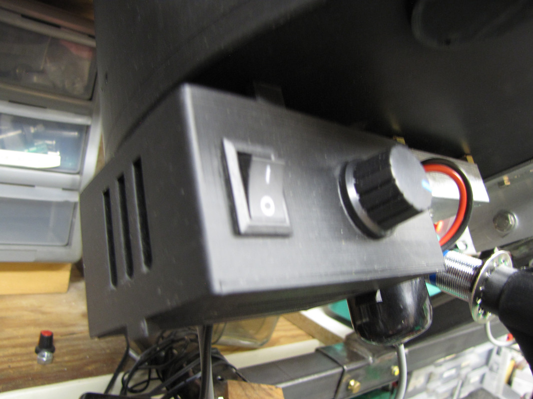
Yes a threaded flange 3/4" black plumbing pipe. I got a 2' section at the H. depot. It comes threaded on both ends. I love the fact that I can swivel the collator off to the side to fill the powder hopper & such. I still can't believe how well it works.

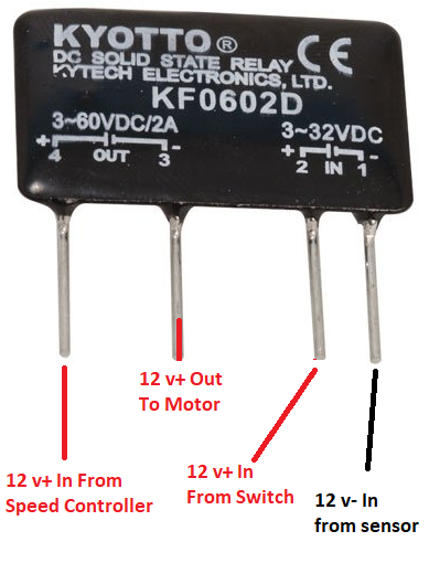
Most common issue is with the proximity sensor wire colors. The Brown wire is positive (V+). The Blue wire is negative (ground), and the Black wire is the signal wire that goes to the Relay in Pin 1. I think its common to mix up the blue and black wires. I did it once.
That's right, I remember........I had those leads reversed, Black from the Sensor, NOT blue goes to the negative "IN" on the Relay. The blue goes to the common negative.....which seems wrong....but it isn't. I mean black in all other cases goes to negative ground so it's easy to get that wrong on the sensor.
Hi.
May i be so rude to ask for stl for this box? I can�t see it in the contributors folder, or is the file located somewhere else?
In one wiring schema I have it seems to show two legs of the relay to be bonded together, is that correct?
Sent from my Pixel 5 using Tapatalk
That's my bad. GWS gave it to me days ago. just been busy. uploading it now. it will be in the GWS file.
Pins 3 and 4 establish continuity for the V+ going from the speed controller out to the motor. Is that what you mean?
Also want to make sure, you are looking at my latest diagram. Did make some changes a month or so ago.
Last edited by TylerR; 01-20-2022 at 10:48 AM.
On December 13 sierra1911 post the following observation:
TylerR responded with the following and posted an updated schematic:Heres both schematics: New one on the left ..... old one on the right......and yes the old one tied two leads together on the relay. I'm sure TylerR tried the new one and it worked too. To be honest I haven't taken the time to change the wiring on mine (wired the old way) since it works fine. Maybe I should?That is a very interesting observation, and I agree with your assessment. I am not sure how much of an issue it is in practicality, but I agree it should be changed. I will take a look at it when I get a chance.
For me (slower than TylerR) I needed another way of illustrating to keep me from wiring it wrong....below is the OLD way. But yes the two leads on that relay are together.....see the wire on the far left. This works, but.......
Update: I just replaced the old diagram with the new one with the circuit changes TylerR came up with so anyone using my box like gentleman called 45acp would have a good crutch to keep the thinking straight.....is can be confusing for sure.

Last edited by GWS; 01-21-2022 at 01:17 AM.
damned if i can find the source, but somewhere i found a wiring diagram (not particularly well done, but good enough), and it appears to show that out (+) and in (+) are wired together, as well as out (+) going to the on/off switch (as well as brown wire to proximity sensor via wire nut).
maybe its wrong. i'm not a great circuit person. do you know of a good/proper wiring diagram for a proximity switch configuration? maybe its there and I just missed it?
didn't see the above reply... i guess I was using an old "method" or wiring diagram. I now see the updated one. I will wire per that one.
Thanks everyone for the help on this!
Steve
Steve
Last edited by MSUICEMAN; 01-20-2022 at 11:27 AM.
I would like to add, these schematics are just our interpretations on how to wire it. What is most important is understanding how a prox sensor works, and how a relay works, etc.... Without that knowledge its a bit like poking at it with a sharp stick. I had to educate myself on relays, because while I had a basic concept, I did not have practical knowledge.
Yes mine, its in the project.
https://github.com/BF556/Feeder/blob...0Schematic.png
Wanted to clarify. I am not a wiring schematic professional. I did not spend time making clear that when two wires cross at a right angle, they are not tied together. In this image, the two red wires indicated in the blue boxes are not tied together. They are just crossing in the diagram.

Last edited by TylerR; 01-20-2022 at 12:36 PM.
your schematic is fine. i was working on the "old" one found in the bottom of the one reply above. yours is pretty darn clear. i hopefully should be able to get it done tonight.
in your diagram you have two + outs for the relay, is that supposed to be one (+) and one negative or are two wires going to the + out pin?
Its labled + and - on the relay, which I have in the diagram. But it is really just a switch between two 12v+ wires. That circuit closes when the circuit on pins one and two close. Which then creates continuity for the 12v+ to flow to the motor.
It might be good to study up on how relays work. This is a good video.
Last edited by TylerR; 01-20-2022 at 05:19 PM.
And yet another version of the diagram, made by GWS to show wire crossovers.

The relay image you just posted is for the old configuration where the leads on the relay are tied together.
Yes, you are right. removing. sorry for the confusion.
also, I changed the #3 pin on your new diagram back to a red -. Since it shows - on the actual relay. Even though its a +12v out. Confusing I know, but it is what it is.
Here is the updated version of the relay:
Last edited by TylerR; 01-20-2022 at 05:29 PM.
Super good video......even I can see clearly now! I heard of relays, had not a clue of what they were for......until TylerR fixed my proximity circuit with it. I burned out 2 speed control circuits thinking they were just the result of cheap Chinese products. I wonder what else I burned up the same way on other projects?
Last edited by GWS; 01-20-2022 at 05:58 PM.
 Posting Permissions


| BP | Bronze Point | IMR | Improved Military Rifle | PTD | Pointed |
| BR | Bench Rest | M | Magnum | RN | Round Nose |
| BT | Boat Tail | PL | Power-Lokt | SP | Soft Point |
| C | Compressed Charge | PR | Primer | SPCL | Soft Point "Core-Lokt" |
| HP | Hollow Point | PSPCL | Pointed Soft Point "Core Lokt" | C.O.L. | Cartridge Overall Length |
| PSP | Pointed Soft Point | Spz | Spitzer Point | SBT | Spitzer Boat Tail |
| LRN | Lead Round Nose | LWC | Lead Wad Cutter | LSWC | Lead Semi Wad Cutter |
| GC | Gas Check |

 Reply With Quote