Damn those things are pretty. HahaOriginally Posted by GWS


|
   
   
|


|


Damn those things are pretty. Haha
Get some measurements across that plate in different areas.... I'm suspecting something might be slightly out of wack with the print....
Even measure the clutch piece... see if it's perfectly round
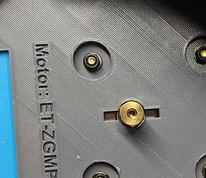
Something is definitely up with your printer Look at the holes.. they are not round
Did you release the cover you created to the Gen pop? I want the lift handle

Be careful.....I'd suspect the picture shooting angle first.....still worth looking closer....but make sure that motor is tight against the bottom of the base....and that the set screw isn't pushing against the hex opening in the plate.
You're the first who's showed any interest....anything I make is always for sale....the price is always the same....free.
That said it needs a lock nut just below to keep it from acting like a second redundant clutch.
Last edited by GWS; 02-17-2021 at 07:32 PM.
Hmmm... That one does look out of round doesn't it. Not sure I've ever really seen that before.
Maybe Tyler can add it to contributions!
Check Belt tension of printer too.... That's a common thing when things go out of round.
Just started my #11 Plate.... My 300 Stuff is all going to be Fire Engine red!
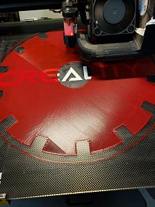
Is that red PLA or something beyond my beginner skills.My #11 was red too.....sister to the green above, but more like the ugly half sister. Looked like somebody poured milk in it....uuuugly! This one looks translucent! Looks great so far....
It's was only on lay 2 when taking that pic.... but it is actually called Fire Engine Red
https://www.amazon.com/gp/product/B0...?ie=UTF8&psc=1
This is the exact problem that I was asking a couple days ago. If you look at his picture, the upper left above Small Rifle and lower Right, above the other "small Rifle" are both touching or close to the base. This is the same plate that I printed and same base, so I am having the same issue. I sanded down my plate, but do not have the motor yet to try and mount and see how it goes. As Tyler had replied to me is that the tolerance is very tight. I was wondering if it was a printer issue on my end.
Last edited by yoterunner; 02-17-2021 at 09:43 PM.
I’m also interested in the handle if you don’t mind sharing it with a newbie to this thread. I’ve been lurking here for a while. I’m just now setup to start on this journey. Once the power situation improves in a couple days anyway.
Assuming it isn’t the camera angle. The back left bolt isn’t threaded as deep as the rest. Also the clutch or hole in the plate is out of round. Zooming in on the first picture the gap is wider towards the rear of the body. It also has the same appearance in the video. Unless that’s how it’s supposed to be?
It still makes me wonder about going back to 179.5mm as the default, but then that creates its own set of issues with other situations. Who would think 1/2mm could make such a difference either way.
I can definitely add it. I am still trying to figure out a good way to add the handle but not require longer screws to come up through, but have not come up with anything yet.
I printed a new cluch plate and also drilled the shaft on the motor so I could thread the screw all the way in on the hex portion from both sides. I *think* that solved the problem. Mostly anyway...I'll keep playing with it to see.
The longer screws are actually a good thing IMO, because it makes the plate, the clutch and the handle one assembly that you never have to disassemble. The only flaw is that if you just use a lock nut by itself, it can turn in there.....meaning, if things loosen up and the clutch needs adjusted tighter, you have to remove the handle first.
So either use a square nut like I did on my first one, that won't turn in the limited space and use the lock nut top side, or do what Ed did and create a keeper for the lock nut. His original idea would work with my handle.....but he went further and made a different design......now it's a matter of which an individual likes.
The remaining flaw that I think you don't like is that there are different brands of lock nuts, and one "keeper" may not fit all....and square nuts may or may not be easy for everybody to find. Perfect would be to have a nylon locking square nut, but they don't exist that I'm aware of. OR.......just press a little epoxy putty in one corner, and the nyloc will stay put for a long long time.....the more I think about it....why make it harder than it has to be.
So you all can see this is a design in process......works for me right now, but will it be attractive to everybody? I doubt it, especially not for people who don't improvise or mod things on their own.
That said I sent TylerR the .STL file as is, but I fully expect it will be improved by me or Tyler or Ed, or someone else.
Last edited by GWS; 02-18-2021 at 12:25 AM.
Oh, btw, what I did to keep the handle lid from being another clutch, is screw on a nut on each bolt to the level just barely above the plate height, then I placed the lid, hed down with regular nuts over the top finger tight against the nuts just below.....they DO tighten up because the bolts are tight from the square nuts (or in this latest case, nylocs) on top of the clutch itself, so the bolt will not turn. I'll go take a couple of pictures to demonstrate....and will post in this post.
Okay, on this plate I used 6-32 flat head bolts 1 1/4" long, through the clutch and nutted with 6-32 nylocs.
Then, I screwed on regular 6-32 nuts to raise the handle enough not to tighten to the plate. finger tight only.
Finally handle is placed and two more regular 6-32 nuts are screwed on finger tight over the top.
There's room for a thin pallete knife to slide in easily underneath.
Last edited by GWS; 02-18-2021 at 12:17 AM.
First off, just want to say how cool this is. Got my first printer a few weeks ago and have been making a few parts for my APP presses while I figure all this out. Have been pretty successful so far and that is a testament to R&D you all are doing here.
Have a hopefully simple question. Is there a adapter/connector or combo that would allow the use of the medium and small APP tubes directly with a bullet feeder die?
I will be building a collator after I get up to speed a bit more. In the meantime, I thought I might manually load APP tubes to supply a bullet feeder die in 9mm/38 and 223. Thanks
Thanks
I don't think that extra 0.5mm caused it. I printed 4 plates with the clutches and they cycle fine. I suspect this has more to do with poor printer calibrations than tolerances.
However, the bottom screw holes of the clutch plates are kind of screw specific in that my two hex screws protrude a little below the plate. It would be nice if there wasn't a bevel for tapered screws and something more cylindrical.
 Posting Permissions


| BP | Bronze Point | IMR | Improved Military Rifle | PTD | Pointed |
| BR | Bench Rest | M | Magnum | RN | Round Nose |
| BT | Boat Tail | PL | Power-Lokt | SP | Soft Point |
| C | Compressed Charge | PR | Primer | SPCL | Soft Point "Core-Lokt" |
| HP | Hollow Point | PSPCL | Pointed Soft Point "Core Lokt" | C.O.L. | Cartridge Overall Length |
| PSP | Pointed Soft Point | Spz | Spitzer Point | SBT | Spitzer Boat Tail |
| LRN | Lead Round Nose | LWC | Lead Wad Cutter | LSWC | Lead Semi Wad Cutter |
| GC | Gas Check |

 Reply With Quote

