I can send you one for The Zyltech Green & Blue Satin composite, but I'm up to my behind in crocodiles until this evening....guess you can add it later.

|
   
   
|


|


I can send you one for The Zyltech Green & Blue Satin composite, but I'm up to my behind in crocodiles until this evening....guess you can add it later.
I can add it anytime. No big hurry.
The new file printed just fine.Originally Posted by TylerR


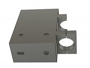
I'm designing a controlbox to be mounted on the pole that the dillon casefeeder mounts to.

So did some testing with my new sensor, and I can't say it detects any further then the other one did. Kind of annoying. So I went back to the drawing board with the drop tubes themselves. The 6mm tube now only has 2mm between the sensor and the bullet column. I am uploading it as a new version (v1.2.8)
So with that said, just about any 18mm dia. sensor with at least 8mm detection should work. One thing I do like about my new one is it is much shorter and compact.
Why have material between the sensor and the bullet at all? Is it to just have a flat surface to stop the sensor at a fixed distance? Why not use a hatch or multiple slot pattern to remove material and possibly have a better chance of eddy currents being disturbed and tripping the sensor. We've used these in some of our instruments at work and the only way to get a solid signal is to have no material in front of the sensor. I know it works so don't take my suggestions the wrong way, simple solutions are the best, and removing material to get to a 2mm wall thickness is really simple.
These inductive sensors don't care about non metallic material in between, just the distance to, and the size and shape of the metal. The bullet column can't be completely open. I have tested the latest and it works flawlessly.
Glad to hear it works with the reduced wall thickness. Simple is better.
So 18mm recommendation with 8mm as the cutoff. Add that to the manual?
Yes, that will work. May want to mention it also needs to be a normally closed (NC) Inductive sensor.
I also added another small electronics box for using the proximity sensor. I shamelessly sole GWS's idea with the slide on lid. Mine is designed for people who want to use jst, xt30 and 12v barrel connectors. It has standoffs for the board but really only the front two can be accessed with a screw driver, which makes it plenty secure. GWS's is better suited for direct soldering.
Last edited by TylerR; 12-20-2020 at 11:44 AM.
Have you updated the rest of the drop tubes? I was just getting ready to print a 9mm one
Yes. Just make sure to re-download the latest. Sometimes I re-post with the same release number if the changes are very minor.
Do you have a Hornady Case Feeder or Bullet feeder installed? If you have a case feeder, I'm assuming you are wanting to "interface" with a bullet feeding version of the collator......so what follows is based on that.
First you have to decide what "feeder die" you will use.....DAA's, Hornady's, or a printed version TylerR created here. That die screws into your LnL adaptor then plugs into your press topside. Then it's just a matter of tying the collator output to that by downtubes, springtubes, whatever you can conjure up. Somewhere in that output you need a switch to turn off the collator when your downtube is full. Bullet stacking is important to some feeder dies, to provide weight behind the feeding bullet to make the die work correctly. Others don't require much weight, just depends on what you decide to use.
TylerR and crew have made downtubes with the off switch fairly close to to press, allowing a short stack before the switch turns the collator off. They are not made to fit Dillons per say, they are for certain bullet feeding dies......some for the homemade printed ones. TylerR is the best source of info on them.
Me, naturally being a perverted divergent, use the older system of filling the whole tube (or springtube) Dillon, RCBS and Hornady case feeder style before the switch turns it off. That means putting a switch high, just under the collator, vs low just above a short stack on top of the feed die.
Now the OTHER interface: the mount for your bullet feeder on your bench is whole nuther thing. Some of the Dillon guys have their bullet feeders mounted to the side of their case feeders. Others mount them to poles, and I think TylerR has a pole mount you can print. I made a horizontal steel tubing rail that I had a nephew weld for me. Your mount will be individual. I've seen Hornady user setups bolt on a mount to their case feeder pole or just a pipe with a pipe flange to the bench.....this is very individual.
I'm going to post this to the forum, because others will have information and input too.
Excellent summary GWS!
And yet I failed to answer his last question....did I design new parts for my press. That's a yes, but again, anything I designed could be used on any press, with the exception of an upgrade to RCBS's case feeder shuttle which I found too limiting .... it works, but only if you crank things slow....it only did 9mm pistol well. It threw .223 rifle across the room, base first. So I added this little green extension to that tiny "V" block they used for pushing cases.....and that's the only part I've made that is machine specific.
As for bullet feeding dies, I use Hornady Pistol bullet feeder dies, and for RIFLE, I use RCBS's new tube bullet feeders. Which are awesome. Some have used RCBS's pistol feeder dies, but I didn't like the plastic inserts held together with rubber bands. The new rifle ball bearing operating dies are another thing....they are awesome, and come with "M" neck sizers.....but they are pricey over $100.
Last edited by GWS; 12-20-2020 at 04:48 PM.
Almost, but the CASE collator is not quite there........Question.......I'm down to the last little pieces to print to finally get my case collator to the ammo production line. I have problems with soldiers.....so these last pieces are what's needed to knock them over. (they DON'T act nice....they jamb the outet.....even slow). So I have the Long Sweeper downloaded.....do I need the regular sweeper and flipper too? IOW's do they work combined or separate ...... wasn't sure from the video?
I assume you mean the longer rifle cases coming up 3 all in a row? If so you want the long sweeper. You mount the sweeper by pulling back on the flipper and inserting it in, so it disables the flipper.
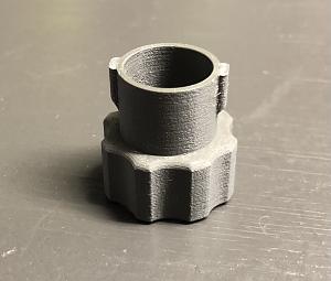
The wall extender is a perfect fit, thank you Tyler!
Here it is installed:
https://drive.google.com/file/d/1JnY...ew?usp=sharing
Looks so nice and it even printed better than the last one; far less stringing.
That's what I guessed but didn't know for sure. The Sweeper is a plug of sorts sticking out far enough to chop heads off.....that works. Thanks. Better get to printing.....
Looks like you're building Darth Vader's Helmet....improved.
I must be missing something here. The switch is rated to 300mA. The motor is rated at 1.3A full load. I finally got mine wired up, and I am using the same exact wiring method GWS posted. But when I try to run the motor with the sensor, it just goes click click and does not actually move. As soon as I remove the switch out of the equation, the motor works perfect. I know the switch is wired correct also because If I swap an LED bulb for the motor it turns on and off perfectly. I would think a relay would be needed to convert the low amperage switch up to the higher amperage circuit the motor requires.
Someone help me out here please.
 Posting Permissions


| BP | Bronze Point | IMR | Improved Military Rifle | PTD | Pointed |
| BR | Bench Rest | M | Magnum | RN | Round Nose |
| BT | Boat Tail | PL | Power-Lokt | SP | Soft Point |
| C | Compressed Charge | PR | Primer | SPCL | Soft Point "Core-Lokt" |
| HP | Hollow Point | PSPCL | Pointed Soft Point "Core Lokt" | C.O.L. | Cartridge Overall Length |
| PSP | Pointed Soft Point | Spz | Spitzer Point | SBT | Spitzer Boat Tail |
| LRN | Lead Round Nose | LWC | Lead Wad Cutter | LSWC | Lead Semi Wad Cutter |
| GC | Gas Check |

 Reply With Quote