This is the thread that I would like to see made a sticky!

|
   
   
|


|


This is the thread that I would like to see made a sticky!

Years after I was doing the modifications on my Mauser parts I got the books Gunsmith Kinks 1& 2.
Funny thing , most of the stuff I was doing was shown in both these books.
I actually combined a couple of the modifications shown in those books, to what I what I was modifying.
Three different modifications shown in the book on the same trigger worked out even better.


This is very interesting to me. Will there be pics coming?
Sent from my SM-A716U using Tapatalk
I can not send any pictures on my computer now for some reason.
I don't do much on computers , cause I grew up without them.
Maybe I should buy a new computer and have my seven year old granddaughter teach me how to use it.
And teach me how to get this new phone to forward pictures to my computer.
But I can and do Text pictures to members that ask.
Just PM me a number to send them to.
It is sad that the original ones in that thread are gone
Last edited by LAGS; 01-05-2022 at 02:45 PM.

Lags, if you're inclined (or able) could you send them to me via email, and I will gladly size them and post them? If this works for you PM me and I'll give email address.
This sounds like something to preserve. I've been noodling something similar but haven't wrapped the brain around it totally....


I built several ball triggers based on LAGS design. Let me rummage through my archives and see if I have any photos. I think that I might even have the pictures from LAGS original thread. I'll post up whatever I can find.
Thank you guys for the Help.
Mechanical things I am great at.
Electronic things , not so much.
Or I would have built a electronic digital trigger for my rifles.
Hay,
Fingers are your digits.
So maybe my triggers are digital
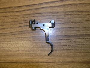
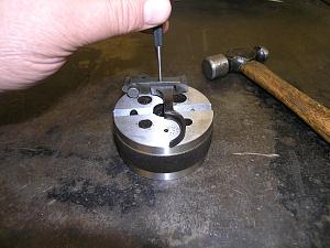
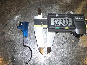
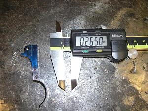
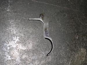
These pictures are from a trigger that I built for a 1894 small ring that I converted to 7.62x39. The first photo is the basic Mauser trigger. The trigger & sear are disassembled by drifting out the pivot pin. (I replace the pivot pin with a dowel pin: iirc it's a 3mm dia. x 10mm long. This isn't really necessary, but I fool myself into thinking that it adds some kind of precision.) After the assembly is apart the first step is to lay out the trigger for cutting the recess for the ball. The width of the cut isn't super critical, but the depth is. If the step on the back of the trigger isn't deep enough the portion of the trigger that your finger contacts will be too far forward in the trigger guard. If the step is too deep the trigger will be too far back in the trigger guard. If the step is way too deep the trigger will contact the back of the trigger guard, and there won't be enough actuation to pull the sear off of the cocking piece. I've found that the best way to cut the ball recess is to remove most of the material with a thin cut-off wheel in a Dremel tool, then make fine adjustments with a small file. Fit the trigger & sear assembly often onto the receiver and sneak up on the proper depth as you go.
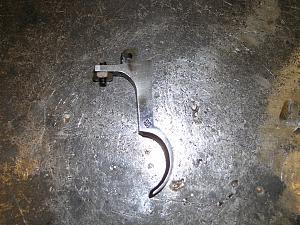
The next step is to install an extension on the trigger for an adjustment screw. I have a TIG welder, but if you don't you can braze on an extension. When you install the extension make it longer than your going to need. It can always be shortened to length after installation,and having it longer makes it easier to hold in place during installation. Welding or brazing should be strong enough, but I'd recommend against soldering. After the extension is installed, drill and tap it for an adjustment screw. I believe that I used 6-32, but an 8-32 would probably work too. Use a long set screw with a hex nut to make the adjuster.
I almost forgot something: Way back at the beginning, very first step: the two lobes on the top of the trigger that originally pull the sear down need to be ground flat. (see photo #3)
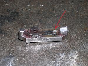
The new camming surface that's going to pull the sear down is going to be a 1/4" ball bearing. This bearing is going to be actuated by the step on the back of the trigger, and will ride against the bottom of the receiver tang. The slot in the sear will need to be opened up for the ball to sit in the sear. This is easily done with a rat tailed file. (picture #8) The finished trigger, ready to install is shown in photo #9. The adjusting screw takes up the slack in the assembly, which reduces the sear/cocking piece engagement and lowers the weight of the trigger pull. Don't lower the trigger pull too much. For safety reasons the rifle must pass a bump test. With the rifle empty, but cocked, smack the butt of the rifle smartly against the floor at least three times. The sear should not come off of the cocking piece. If the action fires the trigger pull is set too low. Also, using moderate force (not gorilla death grip force) cock the empty action and insert the tip if a screwdriver under the bolt shroud. Try to lift the shroud & cocking piece. If the cocking piece comes off the sear and the action fires that's bad, and will need to be addressed.
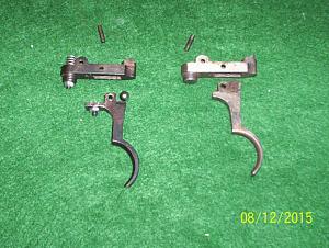
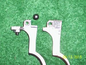
These photos are from LAGS thread on building the ball trigger. In his build he installed an over-travel screw by drilling and tapping through the spring seat on the sear. I had to omit this feature on my build because I was using a spacer in the back of the magazine well, and the over-travel screw & nut would interfere with the head of the screw that was holding on the spacer. The ball trigger was a vast improvement over the military two stage trigger, and works good even without the over-travel adjustment. Thank you LAGS for this great idea.
Here are some more of LAG's pics I didn't take the time to upright them.
Thank you both.
It is nice to know that something I use will be used by others.
It is a Cheap home made upgrade to your rifles and won't detract from it's historical value.
I kept the original triggers for my " Collectable Rifles ".
That way I could put them back to original any time I wanted to.
But these also worked on target rifles and my hunting rifles.
These are way better than the typical " Bubba Fix " that a lot of guys do by grinding down the sear or installing a weak spring to lighten the trigger pull.
I hope some of you try this style of trigger.
It is great to share this kind of info with others.
Oh.
A trigger can be modified in about two hours with simple hand tools like a hack saw , a file and a small round file.
I have done the trigger adjustment extension by Silver soldering or brazing a 6/32 nut to the front of the trigger tab.
It isn't as strong as welding on an extension then tapping it for a 6/32 set screw and locking nut.
But it will work.
Thank you all again,
LAGS. Larry A "Gun" Smith
Last edited by LAGS; 01-05-2022 at 08:05 PM.
Thanks, all involved!
I doubt that I'm the only one checking Sarco for Mauser actions right about now
Sent from my SM-A716U using Tapatalk
I still have 10 Mausers that I need to work on.
5 Yugos ,Two Czech and three Russian Captures.
I am sure I will be modifying triggers for most of them.
I probably have three or four done already on finished rifles in the safe.
Some of the finished ones also have the Hinged Floor plates on the magazines that I built for them , and so will some of the ones I am going to rebuild or customize
LAGS, any time I can help is my pleasure.
Yes, thank you both for explaining and adding the pictures!
@copperlake.
You didn't need to rotate the pictures,
Most guys are just going to do this on the side anyway.
LOL
There is one other thing I forgot to mention , but it is no big deal.
If you want a Super Fine Adjustment.
Use 6/48 adjustment screws.
5/40 also works.
Last edited by LAGS; 01-06-2022 at 11:04 PM.
Hold the phone!! "Some of the finished ones also have the Hinged Floor plates on the magazines that I built for them" LAGS, do you have a thread on this? I've lost count of how many Mauser's that I've seen where some knucklehead has Bubba'd the bottom metal by trying to pry off the floor plate with a screwdriver. A hinged floor plate on a Mauser sporter really adds a touch of class to the build. If you have a thread on making this modification please link to it. If you haven't put up a thread/tutorial on making a hinged floor plate, one would be greatly appreciated.
I can do a thread if someone can help me with the pictures.
Let me see if I still have pictures in my old computer or just take some new ones.
While I am at it , I might send pictures of the Safety Modification for use with a scope.
That too is a simple homemade conversion that people should like to see.
i can't wait to see them too!!!!!!!!
 Posting Permissions


| BP | Bronze Point | IMR | Improved Military Rifle | PTD | Pointed |
| BR | Bench Rest | M | Magnum | RN | Round Nose |
| BT | Boat Tail | PL | Power-Lokt | SP | Soft Point |
| C | Compressed Charge | PR | Primer | SPCL | Soft Point "Core-Lokt" |
| HP | Hollow Point | PSPCL | Pointed Soft Point "Core Lokt" | C.O.L. | Cartridge Overall Length |
| PSP | Pointed Soft Point | Spz | Spitzer Point | SBT | Spitzer Boat Tail |
| LRN | Lead Round Nose | LWC | Lead Wad Cutter | LSWC | Lead Semi Wad Cutter |
| GC | Gas Check |

 Reply With Quote