Load DataReloading EverythingInline FabricationMidSouth Shooters Supply
RepackboxRotoMetals2Titan ReloadingWideners
Lee Precision Snyders Jerky
Page 1 of 7 1234567 LastLast
Results 1 to 20 of 125

Thread: Ogive cutting on a lathe

  1. #1
    Boolit Master

    Idz's Avatar
    Join Date
    May 2013
    Location
    New Mexico
    Posts
    842

    Question Ogive cutting on a lathe

    I'm looking at making some die reamers with various profiles. Some people free-form a curve with files but that isn't reproducible. Others have built/bought a ogive/radius cutting fixture for their lathe but that takes time and money.

    What I am looking at is using the swiveling compound rest as the ogive cutter. My cheap 9x20 import lathe has a one piece swivel base that I took apart and chucked the swivel pin in the lathe. Then using the tailstock drill I drilled a hole in the top of the piece that is concentric with the swivel axis. By using pointed pins I can align the chuck axis to intersect the swivel axis. Then using the crossfeed I can set the ogive radius offset. I can then set the bit and set a stop block on the compound rest so it stops rotating when the swivel to bit point line is perpendicular to the chuck axis. Using the longitudinal feed and swiveling the compound rest I can then cut a precise ogive.

    It works well on my test wood dowel and aluminum pin but I have to make a better bit before I try steel. Has anybody here tried this before to cut a ogive on a reamer? I worry that it may not be rigid enough for cutting steel.

  2. #2
    Boolit Master

    Reload3006's Avatar
    Join Date
    Nov 2011
    Location
    West Plains, Mo.
    Posts
    1,584
    why not make yourself a form tool bit? reproducible every time.

  3. #3
    Boolit Buddy
    Join Date
    Apr 2013
    Location
    West Central Fl
    Posts
    451
    Haven't been able to get a mental picture of what you're doing. But, I have wondered why you couldn't just make a "ball turner", set it for what ever radius ogive you want and have at it.

    CC

  4. #4
    Boolit Man
    Honorstick's Avatar
    Join Date
    May 2013
    Location
    Northwest Michigan
    Posts
    77
    I've been working on the idea of something similar except I was thinking of a fixture that would replace the compound and allow me to swing pretty much any radius arc I wanted within reason based on lathe size.

    I would be interested in seeing pictures of what you're doing or pictures of what others have done to achieve something repeatable that can be done on a lathe.

    Once I get further along with my proof of concept I'll try to post some pics as well.

  5. #5
    Boolit Buddy
    Join Date
    Apr 2013
    Location
    West Central Fl
    Posts
    451
    Idz,

    try PMing member sprinkintime. I did and asked about his ogive fixture. He sent me pics of his. I can't recall what thread it was in, but he offered to send pics to another member. I pm'd him and he sent them to me also. I don't want to "release" his material without consent, but he was having difficulty posting pics IIRC.

    CC

  6. #6
    Boolit Master

    Idz's Avatar
    Join Date
    May 2013
    Location
    New Mexico
    Posts
    842
    Thanks for the replies. I have looked at a number of radius cutting fixtures but don't need another project so was hoping to adapt the existing lathe parts. The only difference I see between the fixtures and compound rest is the fixture has the ability to locate the swivel axis to the lathe axis. By drilling a hole in the compound rest that is concentric with its swivel axis I can then locate the two axes. My only other concern is if the compound rest is rigid enough while cutting steel. I know it works fine for wood dowels and aluminum test pieces.

    Example: cut a 5 ogive on 0.22 diameter rod
    1) Chuck a pointed pin and insert a correct length pointed pin into the swivel axis hole drilled into the compound rest.
    2) Adjust cross feed and long. feed so the pin points touch. Lock the long. feed
    3) Offset the crossfeed by 5 ogive (1.1) Lock the crossfeed
    4) Adjust the cutting bit point to touch chucked pin point. The swivel point and bit point now form a line perpendicular to the lathe axis. This makes the swivel circle tangent to the lathe axis.
    5) Adjust stop block on swivel so it can't swivel past the tangent.
    6) Chuck up the 0.22 rod to be machined
    7) Unlock and adjust the crossfeed by the material radius (0.11) so the bit touches the OD. Lock the crossfeed
    8) By using the long. feed and swiveling the compound the ogive can now be cut

  7. #7
    Boolit Man
    Join Date
    Oct 2006
    Posts
    85

    Rotozip ogive grinder

    Click image for larger version. 

Name:	283.jpg 
Views:	1418 
Size:	47.8 KB 
ID:	73933

    rotozip tool used for grinder, not a clear picture but u can get the idea of layout for adj ogives

  8. #8
    Boolit Master
    Join Date
    Mar 2013
    Location
    seated with Him in the heavenly places in Christ Jesus (Eph 2:6)
    Posts
    1,192
    teddy, found your pic here, looks nice:


    http://castboolits.gunloads.com/show...nt+forming+die

  9. #9
    Boolit Master

    Idz's Avatar
    Join Date
    May 2013
    Location
    New Mexico
    Posts
    842
    That's a neat way of making a toolpost grinder. The rag is good to catch the grit. I assume you setup to cut a ogive the same way I do by aligning the swivel and chuck, and then offsetting the swivel? What is the line of holes for that are perpendicular to the swivel axis holes? I assume your rig is attached to the crossfeed slide? Is there a fine tune on the rig to compensate for grinding wheel wear?

    thanks

  10. #10
    Boolit Man
    Join Date
    Oct 2006
    Posts
    85
    The holes are to set the ojive, the present setting is a 6 ojive, two holes from the top end is approx 9 ojive.
    A different size wheel will change the ojive. It is adjusted for wear as you use it. The cross slide is used to feed in small amounts as you grind the ojive.

  11. #11
    Boolit Master
    Join Date
    Mar 2013
    Location
    seated with Him in the heavenly places in Christ Jesus (Eph 2:6)
    Posts
    1,192
    so teddy, so i understand how you use it, you are advancing the cross slide forward toward the blank with attached grinder, and then you are just rotating the roto zip in/out to grind off material, then rinse and repeat until the proper OD is achieved?

    once you have formed your ogive, do you mill out some material to make it as a reamer? if so, how many "flutes" are you milling out?

    when the reamer is done, you just ream out the die until you have the correct depth for the bullet, then polish/lap the die?

    how are you checking progress as you lap, do you cast lead inside to measure?

    sorry for all the questions, i just dont get this yet... i am in the middle of making my 22LR to .224 6s and i have made the derimmer, core sizer, core swager/setar, and now i am at the home stretch with the point forming die... thanks

  12. #12
    Boolit Master

    Idz's Avatar
    Join Date
    May 2013
    Location
    New Mexico
    Posts
    842
    Now I'm confused. I would think you would align the swivel and chuck centers, use the CROSSFEED to offset to the correct ogive, then lock the crossfeed and use the LONGITUDINAL feed to adjust cutting depth. Also, just how are you adjusting for wheel wear?

    thanks

  13. #13
    Boolit Master
    Join Date
    Mar 2013
    Location
    seated with Him in the heavenly places in Christ Jesus (Eph 2:6)
    Posts
    1,192
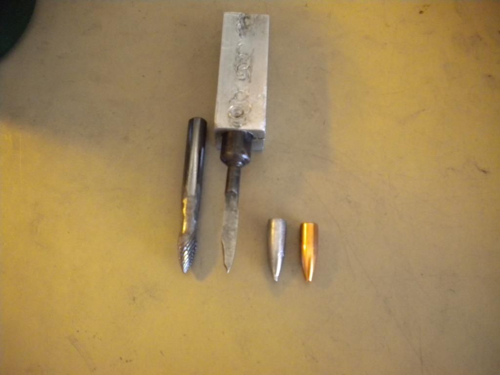
    here is my first attempt at ogive cutting on the lathe:


    from left to right:

    -0.25 burr that i ground down to 0.218 or so, to rough out the ogive
    -my first attempt at a d-reamer, 0.224 6s profile, but the OD was ~ 0.220
    -lead casting of the die (the tit on the meplat is from the ejection punch hole)
    -the production bullet that i am trying to copy (this is a Sierra 55gr)

    the die flared out and is about 0.230 at the base, and i learned a few lessons on this one... i will attempt another this weekend and be much more careful while boring...

    the d-reamer was made with w1, the profile was made using two angle cuts and then shaping with a file and sand paper, then i milled it in half and filed it smooth, heat treated water quenched then tempered, then ground out the back of the spoon, then sharpened with a diamond hone and it cut pretty smooth and i was surprised how smooth it cut
    Last edited by Cane_man; 06-22-2013 at 03:16 PM.

  14. #14
    Boolit Buddy
    Join Date
    Apr 2013
    Location
    West Central Fl
    Posts
    451
    Cane,

    Looks like you are making progress. Did you predrill the hole for the burr? If so, with one bit or several different sizes, feeding in a little further each time, as they got smaller? Do you think the die flared because of the burr or the reamer? Or maybe lapping? What was your die material. Grade 5 or grade 8 bolt, or 4140 PH? Save it for making .243, it's not a bad die, it just hasn't reached final dimension.

    CC

  15. #15
    Boolit Master
    Join Date
    Mar 2013
    Location
    seated with Him in the heavenly places in Christ Jesus (Eph 2:6)
    Posts
    1,192
    i wussed out and used 12L14 because i didnt know how it would turn out...

    i predrilled as much as i could or dared to, but used the burr to hog out most of the material so i didn't really have to predrill... i drilled the 1/16" ejection rod hole and that was it before reaming... i fed the d reamer in cutting a little at a time, retract it and cleaned it off... a pile of tiny metal flakes would be on top of the reamer but they were really fine almost like powder and the cutting was pretty easy... that diamond hone gave it a really decent edge and it cut pretty smooth... i think the die flared because the reamer was not perfectly square/parallel to the die body... for sure i could keep boring it out to 0.236 or so and salvage this for the 0.243 project which is next wasn't as hard as i thought and it was a blast

    i am thinking that making a 4 flute reamer is the way to go... this way i can chuck it in the tail stock and i wont have to worry about any alignment problems and i may get an even smoother finish... i could rough cut hog it out with the d reamer, then finish with the fluted reamer

    me and the wifey gotta do some stuff then later today i may do another with some O1

  16. #16
    Boolit Master

    Idz's Avatar
    Join Date
    May 2013
    Location
    New Mexico
    Posts
    842
    Curious as to why you cut off the back side of your reamer. I thought the reason d-reamers work is the 1/2 diameter reamer couldn't move around in the hole and chatter.

  17. #17
    Boolit Buddy
    Join Date
    Apr 2013
    Location
    West Central Fl
    Posts
    451
    Cane,

    I thought I noticed your D reamer was mounted in a boring bar holder. I was wondering why you didn't chuck it up in the tailstock, if you had a chuck to fit it.

    Idz, has a good point. I haven't seen any D reamers with the back side cut/ground off.

    CC

  18. #18
    Boolit Master
    Join Date
    Mar 2013
    Location
    seated with Him in the heavenly places in Christ Jesus (Eph 2:6)
    Posts
    1,192
    the way i understood a d reamer, it is also known as a "spoon", is that it is made like a boring bar with only one cutting edge... the way i cut it in half i could only get relief for the cutting edge on one side, so i just ground off the other side so it wouldn't bind up and cause chatter... i didn't get any chatter from this reamer, but i was only cutting 12L14 which is highly machinable... i really want to make a 4 fluted reamer next, and i finally figured out how i can do it with my lathe by lowering the center line of the part below the axial center line of the lathe...

  19. #19
    Boolit Buddy
    Join Date
    Apr 2013
    Location
    West Central Fl
    Posts
    451
    A D reamer only has one cutting edge is correct. The trailing edge doesn't cut due to the rotation of the material. If you reversed direction then the opposite edge would cut. I'm not sure that it matters really whether the trailing edge is left intact or cut/ground off. Some tend to believe that the trailing edge maintains contact with the wall and stops any possible chatter. I can't say, as I have no experience yet. Still need to heat treat and temper my D reamers.

  20. #20
    Boolit Buddy
    Join Date
    Apr 2013
    Location
    West Central Fl
    Posts
    451
    Came across this on youtube. Not sure yet what the difference is in turning a ball/sphere and turning an ogive/parabolla yet. Still studying that one. Need a compass to do some drawings with.

    http://www.youtube.com/watch?v=s_KRElCauTM

    CC

Page 1 of 7 1234567 LastLast

Posting Permissions

  • You may not post new threads
  • You may not post replies
  • You may not post attachments
  • You may not edit your posts
  •  
Abbreviations used in Reloading

BP Bronze Point IMR Improved Military Rifle PTD Pointed
BR Bench Rest M Magnum RN Round Nose
BT Boat Tail PL Power-Lokt SP Soft Point
C Compressed Charge PR Primer SPCL Soft Point "Core-Lokt"
HP Hollow Point PSPCL Pointed Soft Point "Core Lokt" C.O.L. Cartridge Overall Length
PSP Pointed Soft Point Spz Spitzer Point SBT Spitzer Boat Tail
LRN Lead Round Nose LWC Lead Wad Cutter LSWC Lead Semi Wad Cutter
GC Gas Check