For a variety of reasons I wanted a collet chuck for my CNC lathe. I contacted my Haas dealer and got a recommendation for a pneumatic 5C collet closer from a company called Royal Products. They gave me the name of the closest dealer, and I ordered the unit. The dealer said that Royal had a two week lead time. I paid for the unit on a Thursday afternoon and the next Tuesday I had two packages on the front porch. Apparently the Haas TL1 is popular enough that it had its own item listing, so they must have had a finished unit in stock. (Royal makes collet closers for almost any lathe, but a lot of times there are key parts that need to be modified to make a custom fit.)
One box had the collet closer assembly, consisting of the piston and drawtube (which installs from the outboard side of the spindle) and the spindle nosepiece (which installs from the inboard side of the spindle). There was also a collet wrench, to be used when changing collets.
The other box was a hand valve air kit, which included a hand valve (decided on that instead of the foot valve as I was afraid prosthesis might make it tough to operate) and a luber/regulator pressure gauge assembly.
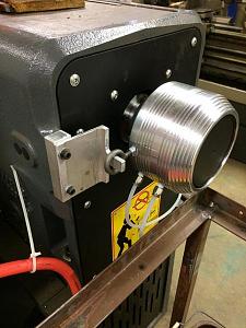
You can see the nosepiece in the first photo. Installing it requires removing six cap screws that hold the chuck to an adapter plate, and then the screws that hold the adapter plate to the spindle nose. The nosepiece bolts directly to the spindle nose.
The piston snd drawtube assembly goes in from the outboard side, There are four cap screws that hold the assembly to the outboard end of the spindle. The clearance was tight enough that we needed to cut off the short end of an Allen wrench to get it to fit. (This will definitely be the slowest step in any changeover) You can see from the last photograph that an anti-rotation mechanism is necessary to keep the piston assembly from rotating. The factory cure was a 3/8 threaded rod with several nuts and washers and a rubber hose to fit over the rod for padding. Installation would require drilling a hole in the vented end panel, then removing the panel and installing the threaded rod with nuts on either side, then putting the panel back in place. The rod would be sticking out all the time, even when not using the air chuck. We used a piece of aluminum channel with one leg milled off and the other leg narrowed to fit into ring. An aluminum spacer block shims it out to the right point, and two 1/4-20 screw holes that were already in the machine's casting were used to secure it. The air chick moves about 1/4"-3/8" axially, so the bracket allows that motion but prevents rotation.
The air valve was mounted on a piece of aluminum angle which at this point is C-clamped to the machine bed. We plan to refine this, but it works for now. When we take off the piston and drawtube assembly we will also take off the hand valve with it as a unit. The regulator is connected directly to a pressure line, with the outflow connected to the air valve with a quick diconnect fitting. The regulator is mounted inside the rear machine guard sheet metal, so I can just drop the hose straight down after it is disconnected and it is out of the way.
This will allow us to machine smaller diameter material (limited to 1/2" with the 3 jaw), and speed up part changes, while reducing the effort required. It is also a little safer, since there is nothing on the outboard end of the spindle that rotates, so you can't snag loose clothing. It is also really quiet and uses just a tiny amount of air for each clamp/unclamp cycle.
So far I'm pleased.

|
   
   
|


|

 Reply With Quote

 W.R.Buchanan