Deleted until I get help. This the best impact impression I was able to make.

|
   
   
|


|


Deleted until I get help. This the best impact impression I was able to make.
Last edited by Ramson222; 09-17-2018 at 11:31 PM.
I designed a couple of molds for my 45 win mag, one is a smooth side no lube grooves and 285gr and it cast very easy.
The other is a 300gr with a lube groove and it cast well also.
Last edited by 475AR; 09-02-2018 at 11:32 PM.

Let me know when your done with the design. The only thing I've tried in mine is the Lee 300 gr.
Best it's shot so far was a 1.1" 100 yard group PC and GC using ACCOWW alloy with 2% pewter added in my American using 35.5 gr of h110. I'd like to see a Gould boolit GC for it that weighs 280-300gr.
I think the Gould boolit with a gas check would be the cats rear end in a bushmaster.
I'm wanting more of a Spitzer shape, I already have a flat nose kieth bullet, it doenst shoot well at all. 8" at 100 was the best I could get. That gould bullet is almost exactly what I want, Tripplebeards
Last edited by Ramson222; 09-02-2018 at 08:16 PM.
I need to try some different powders and boolits out of my rifle. I've been experimenting more with my 77/44 and have tried four alloys bad two powders so far. Best group has been .6". I haven't put the time in on my bushmaster yet because I wasn't excited about my boolit choice/ choices available. I just ran h110 up and down and called it.


From time to time I have wished that I had a 450 Bushmaster.Originally Posted by Ramson222

Now, again, I wish that I owned a 450 Bushmaster.
At this stage of the game, I will probably never have a 450 Bushmaster.
But, if I did have a 450 Bushmaster, this is what I would do.
First off, since the cartridge is rimless and straight walled, it head spaces on the mouth of the cartridge case and this means that the end of the chamber has no taper to ease the transition of an over groove diameter bullet.
The first thing I would do is make a chamber impact impression of the chamber to determine the exact configuration of the step, free-bore, leade, groove, and bore dimensions.
Assuming that an impact impression would be identical to the SAAMI specs, this is what I believe should work:
SAAMI shows that the chamber has a long free-bore with a diameter of 0.4530". To preclude the shaving of lead, I would like the bullet to be cast from water quenched wheel weight metal, powder coated and sized to a diameter of 0.4525".
I used the Precision Cast Bullet Design ~ Ultimate software application to work up this bullet design.
Using Ransom222's observed dimensions and combining them with the SAAMI specs, dimensions were entered into the Chamber Module of the Ultimate application and an image was drawn and saved on my computer
The Cartridge Case Module in the Ultimate application was used to draw and save a neck sized image of the 450 Bushmaster.
Using the Computer Bullet Design in the Ultimate application, the exact linear and radial dimensions of the bullet were calculated and sent to the Cast Bullet Design application. The design was easily modified to produce a grooveless powder coat design with the appropriate nose configuration and length to achieve my goal of 330 grains.
A scaled image of the bullet was drawn and saved on my computer.
The Overlay module from the Ultimate application was then used to retrieve, overlay and position the cartridge and bullet images onto the chamber image to visually inspect and confirm the fit of the components.
Now, instead of buying several molds in the hope that one of them will be a good fit, I could order a custom mold that I know could perfectly fit my wannabe chamber configuration.
Whether or not that bullet would shoot well would remain to be seen. But usually, when the old adage of "Fit is King" is adhered to, a bullet has a much better chance of being a real tackdriver.
Here is a large image of the bullet to case, chamber throat fit.

Last edited by Tom Myers; 09-04-2018 at 11:34 AM.
Tom, you are going to make me add the ultimate to my advanced version...
I will email you on how you get the drawing to not show where the lube grooves were on designs that are groove less. I love all of your software, which by the way has made me order more molds then I probably should have.
Tom, i've gotten every thing read for a chamber impact impression. However I haven't done it yet. Is it as simple as clambering a slug a using a rod and hammer to expand it. I want to make sure before I destroy a good case. Also I need to get new calipers, any measurements I posted were off.
Last edited by Ramson222; 09-04-2018 at 05:38 AM.
Ramson222,
Yes, a chamber impact impression is fairly simple if you have the right stuff and use it correctly. click the link below for the internet copy of the help file page that is contained in the Precision Cast Bullet Design Ultimate software application describing a method that works well.
The help page describes using a gas check on the bottom end of the rod. That works quite well if your rod is of sufficient diameter to be a snug fit in the gas check cup. If the rod is too small, it can sometimes punch through the gas check and be difficult to remove. An alternative to the gas check is to use a wad of paper towel on top of the lead slug.
Chamber Impact Impression Help Page.
This page describes the method that I use and, over the years, it has worked well, without any damage to myself or many rifle and pistol barrels. If something in the instructions is not clear, don't hesitate to ask questions.
I suspected that your measurements might be a tad off when I saw the groove diameter listed at 0.452 and the bore diameter listed at 0.4502". That implies that the grooves in your barrel are only 0.0009" deep.
When you measure your impact impression, beg, borrow or appropriate a clutch type micrometer, not a set of calipers. Most any brand of micrometer with the little slip clutch adjustment knob, even with a novice user, is capable of 0.0001" accuracy whereas calipers, at best, are accurate only to around 0.001" or 0.0015".
Is it possible that when measuring your bore diameter that your reading of0.052" was taken with caliper anvils were resting on the corners of the groove impressions and not contacting the impression of the bore area?
I sometimes take a sharp knife and, very carefully, just scrape the raised corners of two opposite bore impressions down just enough so that the micrometer anvils can contact the surface of the bore impression.
Last edited by Tom Myers; 09-04-2018 at 08:20 AM.
475AR,
I'll try to answer your question here as other users may have the same question.
A simple method usually only requires three edits to a grooved design.
1.) Edit the number of Body Bands to read "0".
2.) Edit the [ Base Band Length ] to equal the [ In-Case ] value.
3.) Edit the [ Groove bottom dia. ] to equal the [ As-Cast Diameter ] value.
This will increase the bullet weight by a small amount.
If bullet weight is critical, simply increase or decrease, in small increments, the bullet length, incase length and base band length by the same amount until the desired weight is reached.
Changing only these three values will maintain the configuration of your existing front band and nose details.
Below is the Computer Design input data that produced the initial image, without any editing, that the computer designed and sent to the Cast Bullet Design Advanced application for the dimensions of the chamber and the cartridge.
(The SAAMI specs that were used in conjunction with Ransom222's data to produce data entry values for the Chamber Drawing application)
(The chamber dimension values that were entered for Ransom222' chamber)
(The values generated for the bullet design by simply entering a proposed bullet velocity and then using the tab keys to step through the data calculations)
(Note - the computer generates cast bullet weight using Lyman # 2 alloy. Wheelweight metal will give significantly higher results)
(This is the design that was sent to the Cast Bullet Design application)
If not for powder coating the bullet, the only change I would make would be to add a small radius to the meplate edges and it should work fine as is.
To alter the design to a smooth sided bullet, the following changes were made.
Set the front band = to 0 and add its original value to the incase length to achieve a uniform body length.
I prefer Secant Ogives on my bullets, when they can work, so the Nose Type was configured as a Secant Ogive with a slightly smaller meplate
The Base Band Length was edited to equal the In-Case length, Body Bands set to 0 and the Groove Diameter value set to equal Body Diameter.
The Bore Ride length was set to zero and the Bore Ride Diameters were set to equal the body diameter So that that Secant Ogive base would be the same diameter as the body diameter.
The Incase, and base band lengths were shortened by 0.002" to slightly back off the ogive contact at the lands. (can you say O.C.D.)
The bullet alloy was changed from Lyman #2 to Wheelweights.
The Secant Ogive radius was edited to tweak the wheel-weight bullet weight to a precise 330 grains. (again O.C.D.)
By chance, an Ogive Radius length of 2 nose diameters was perfect. And this is the result:
(Final design sketch for the 450 Bushmaster powder coated bullet)
Hope this helps.
Last edited by Tom Myers; 09-04-2018 at 10:40 AM.
Thanks Tom, I will have to try what you explained and will design another bullet or 20...
Tom, I already have a set of 1" mitiyoyo micrometers that are good. I'm a little confused as to where the measurements are supposed to be made.
Last edited by Ramson222; 09-04-2018 at 03:09 PM.
Tom, I forgot to mention that wheel weights are unattainable here.
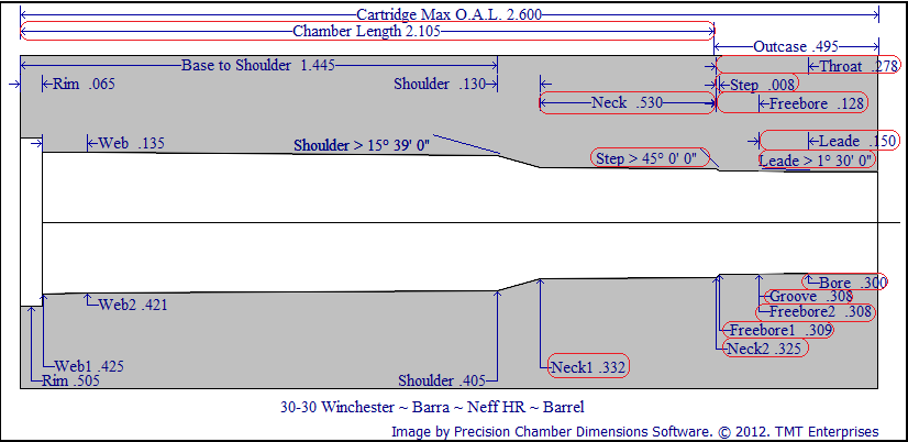
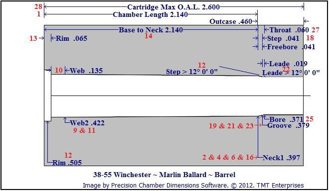
The values enclosed in red are the more important values needed for bullet design.
The values circled on the top of the image are the critical linear values and can be measured with calipers.
Each of the linear measurements are best taken from two measurements from the base of the impact cartridge to each end of the linear section and then subtracting to obtain short linear values at the shoulder, neck and throat of the chamber. Values of precision to at least 3 decimal places are sufficient.
The values circled on the lower part of the image are the critical radial values. Each of radial values are best obtained using a micrometer to measure insure a precision of at least 4 decimal places.
Click the links below for an example of the values that can be used for each type of chamber.
When the Ultimate upgrade is used, all of the labeled dimensions are used to enter data into the Chamber Dimension database shown below.
Different chamber types ( Rimless, Rimmed, Straight walled, Bottlenecked and Belted cartridge types ) sometimes require separate data entry windows fields, however, in most cases the software automatically changes the labels and data field visibility. Revolver cylinders use a different page for data entry.
Study the help pages in the links and the various critical dimensions should become more evident.
Some values such as shoulder angles and step angles may be entered manually or automatically calculated when certain linear and radial values are entered.

Last edited by Tom Myers; 09-09-2018 at 07:52 AM.
Use whatever alloy you have. if you only have pure lead, obtain some chilled shot and add an ounce or two to each pot. The arsenic and antimony will produce a harder bullet when water quenched.
Duplicate
Last edited by Tom Myers; 09-05-2018 at 08:26 AM. Reason: duplicate
Duplicate
Last edited by Tom Myers; 09-05-2018 at 08:29 AM. Reason: Duplicate

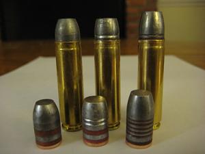
On the left is my 250 grain design, middle is Lee 300 and on the right I believe is the RD 425 grainer.
BD, you using a bolt gun or AR?
Made this impact impression yesterday, does it look good?Attachment 227154Attachment 227155
Last edited by Ramson222; 09-17-2018 at 11:30 PM.
 Posting Permissions


| BP | Bronze Point | IMR | Improved Military Rifle | PTD | Pointed |
| BR | Bench Rest | M | Magnum | RN | Round Nose |
| BT | Boat Tail | PL | Power-Lokt | SP | Soft Point |
| C | Compressed Charge | PR | Primer | SPCL | Soft Point "Core-Lokt" |
| HP | Hollow Point | PSPCL | Pointed Soft Point "Core Lokt" | C.O.L. | Cartridge Overall Length |
| PSP | Pointed Soft Point | Spz | Spitzer Point | SBT | Spitzer Boat Tail |
| LRN | Lead Round Nose | LWC | Lead Wad Cutter | LSWC | Lead Semi Wad Cutter |
| GC | Gas Check |

 Reply With Quote