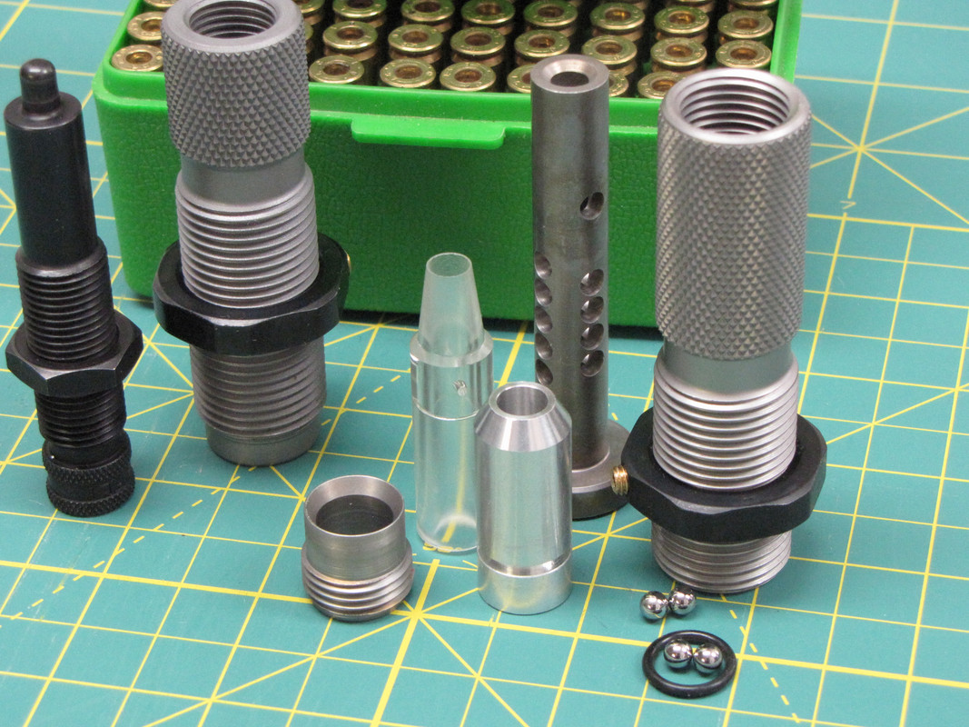
I have a question for Rage 01 or anyone else that can explain this to me. These dies usually have two levels of holes where the ball bearing goes. We can see this on Rage's screen shot. I understand this is supposed to accommodate different length bullets, but I still don't understand how or why its necessary. Also, how do you really determine how far up to put the holes? Someone please educate me.

|
   
   
|


|

 Reply With Quote