Hatch,
The only thing to watch out for is the grooves in that section that the plates slide in to. The tolerances there are fairly tight, so the plate slides in but doesn't flop around.

|
   
   
|


|


Hatch,
The only thing to watch out for is the grooves in that section that the plates slide in to. The tolerances there are fairly tight, so the plate slides in but doesn't flop around.
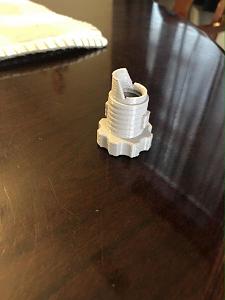
For 223 I tried using the main body adaptor with the smallest hole and the section cut in the middle but the bullets kept getting caught up on the top flat area along the outer edge so I sawed off one side and shaped the round with an exacto and it falls a lot better.
This is my ruined base about a 1/16" thick.
This is the warped corner I'm going to dip in the water....
filled a pot with water....boiling.....dipped the corner in and it immediately softened and drooped, but didn't melt. Placed it on the counter, immediately pressed a heavy flat surface to it. Result below:
Works, but to a point.....it appears that the stuff has a memory, so it flattened well, but it's only 1/16" thick. I don't know how a tall piece would work.....probably ruin it. Putting something on top to hold it down would just as easily deform stuff that is above the warp. On your complicated piece ...... I wouldn't, but on the other hand, if you were to be able to control the dip, and only dip only the bottom, maybe the top wouldn't be affected by weight on it. I'd probably try that, but I didn't wait 5 days for a print, either.
How do you guys use set screws to adjust the flipper plates?
I appreciate that feedback. I have not done any testing with smaller bullets like .223 yet. That part is actually a carry over from the mods version of Mike's original feeder. I have not modified it in any way. I was never really sure why he designed it the way he did with the notch. Once I get done with base up case feeding I will do some testing with .223 and .308 caliber bullets, and will most likely make changes to that part.Originally Posted by Fil131

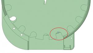
There is a hole in the back of the plate. You can adjust the position of the plate by putting a screw in and experimenting where the plate should be to get the bullets turning reliably. So for .223 you would start with the small pistol turning plate, insert the screw and adjust it to where it needs to be to get it working. Once you have it set for that bullet you shouldn't have to ever adjust it again.
Once I get to it, I will create a small and large rifle plate that hopefully will handle the more common calibers.
Edited to add more detail:
When adjusting the plate, you are setting the distance between the collator plate and the ridge on the turning/slide plate. You want just enough ridge exposed to allow base down bullets to ride the ridge, and nose down to fall off the ridge. The smaller the caliber the further out the ridge needs to be. Here is a screen shot from my CAD to show the ridge distance marked by the blue line:
Last edited by TylerR; 10-15-2020 at 01:42 PM.
Guess I need to print more turning/slide plates. I was attempting to use the two and have a way to move them for different calibers but that's more tedious than making more and having a set screw for each one set to the bullet and caliber I'm loading.
Yes. What I am attempting to do is cover most common pistol and rifle calibers with a "Small" and a "Large" for each. So basically 4 setups. That is what Dillon does for their brass collator. Two pistol plates and two rifle plates.
Amazon special arrived. Appears to be a solid unit. Time will tell I suppose.
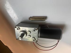
I did design a base around the schematic for that motor. Couple of issue I ran in to. The motor is long enough where it will interfere with the mounts I have for the feeder. That was also true for the FC555 motor, but I was able to create holes to allow you to mount it in 3 different directions. With the motor you have, I can not do that because the mounting holes align in a way where they partially overlap if you change the orientation 90 degrees. So not sure where to go with that. Currently I have it where the mount would interfere with a rear mount, which would allow a mount to the side.
I’m happy to try whatever you have. I wanted to hang it on my Dillon case feeder anyway, in fact that’s what’s on the printer now. That would work on the side right?


Wow this thread has grown since I lasted logged in 1500 odd post. I got some reading to do. On the bright side I finnal got my case and bullet feeder working reliably on my load master.
Sent from my SM-N970U using Tapatalk
"Speak softly and carry a big stick; you will go far."
~Theodore Roosevelt~
Cool, yes it would. I just posted a stl "motortest.stl" that you can print to confirm the hole spacing, before you try and print the whole base. Let me know how it goes.
TylerR: This is an xray of the .223 downtube I designed today.....it goes through the tee and into the upper part creating a funnel before it gets to the sensor, and offsets the center toward the sensor as it passes. Have not tried it yet but I may have to transition more at the angle.....probably depends how long your bullet is..........concept anyway.
Sending you the STL to examine.

Last edited by GWS; 10-15-2020 at 08:03 PM.
I like it. I bet creating that offset tube inside was fun in 3d cad. That one would take me a bit to get right.
If it gives trouble at the angles, I can create a slightly curved polyline and sweep the circle down it......I was just lazy today and thought it might just be fine the way it is.
I didn't add threads at the bottom, because I don't have any springs that small....just tubing. But we can add that if I have some spring thread specs. What I did add at the bottom was a 15mm high inlet to stuff a 1/4" O.D. clear tube up there.
May print one tonight and see if it works, ok. I'll be printing the jumbo size base soon for rifle cases for my PC7 press.
Last edited by GWS; 10-15-2020 at 08:06 PM.
Tyler, the four mounting screw holes line up perfectly, but the center motor shaft hole is too small. Since the motor has a fairly short shaft that hole needs to be opened to .75
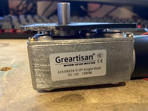
I wasn't aware that area was raised. Looking back at the schematic it is 19mm diameter. I will open it up to 20mm. It has been posted.
You are a gentleman and a scholar. I shall report back in 48 (!!) hours.
Cheers! And good luck with the print!
 Posting Permissions


| BP | Bronze Point | IMR | Improved Military Rifle | PTD | Pointed |
| BR | Bench Rest | M | Magnum | RN | Round Nose |
| BT | Boat Tail | PL | Power-Lokt | SP | Soft Point |
| C | Compressed Charge | PR | Primer | SPCL | Soft Point "Core-Lokt" |
| HP | Hollow Point | PSPCL | Pointed Soft Point "Core Lokt" | C.O.L. | Cartridge Overall Length |
| PSP | Pointed Soft Point | Spz | Spitzer Point | SBT | Spitzer Boat Tail |
| LRN | Lead Round Nose | LWC | Lead Wad Cutter | LSWC | Lead Semi Wad Cutter |
| GC | Gas Check |

 Reply With Quote

