OpenSCAD is used to generate custom collator plates.Originally Posted by thump_rrr

DSM is the program all of the source files for the project were created in. (Except the collator plates)

|
   
   
|


|


OpenSCAD is used to generate custom collator plates.
DSM is the program all of the source files for the project were created in. (Except the collator plates)
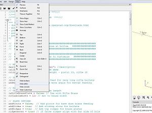
The question I have is how do I use the custom collator generator from the screen shot I posted.
According to the instructions in the manual I should see the collator plate settings on the left.
This is where I am stuck and could use a bit of assistance.
If there was a read me file which specified what plates do what calibers maybe that would clear up the confusion.
The help is very much appreciated.
Go to "View" and uncheck "Hide Editor"
Thank You very much.
Now everything makes sense.
EDIT: Maybe a little note in the manual can save non computer literate people a lot of frustration.
Thx for the feedback. I will add a note
Please put your feedback for the manual here:
https://docs.google.com/spreadsheets...c1k/edit#gid=0
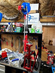
I finally got around to setting up the collator for case feeding the LNL AP. It seems to operate well in my limited testing. Next I plan on redoing the electronics box on the collator connected to my XL 750 and switching from using an optical sensor to proximity. Mostly because the wiring end up being cleaner. This will give me a chance to try my hand at making custom holes from template.
Hey TylerR - When you're creating holes for connectors, how much tolerance do you leave? For example the 4 pin connector I have is is 12.5mm x 5.75mm. I assume making the holes exactly that size is a bad idea. As always, thanks for the help!
I wouldn't want to share my Gcode file, as it may not be right for your printer....
If you followed the instructions on creating a Collator plate in the Documentation, and then used your slicer, with the video.... You should be all set.
Yes, I always add some clearance. people can also make things bigger if they need to. And I use super glue to make sure they stay in for good.
Do you have a rule of thumb for how much clearance to add?
Thanks!
Not really. it depends on the part. .2mm is a good place to start. Then it's print, test, change, print, test, change.........
Hey everyone,
I just wanted to check to see if anyone would feel they'd benefit for a guide on how to add holes to the electronic box templates. I did it for the first time this weekend and it was pretty trivial in tinkercad. I think the biggest hang up I had was trying to figure out how to reverse the work plane (shift click).
TylerR - Another dumb question for you. For whatever reason the the "Brass_Slide_Adjuster" that fits into the "Brass_Slide_Plate" is loose enough to where it will occasionally get pushed open more causing my 300BLK brass to fall base up instead of down. I wasn't sure if I should just try printing it again and hope for a tighter fit or if a more robust solution would be in order such as having multiple size sliders or spacers or some sort of locking mechanism to make it so the slide adjuster can't move. Thoughts/suggestions would be appreciated as always!
I just printed a slider for each (.308 & .223) and an "adjuster" for each and marked, then silicone glued them where I wanted them. I prefer not having another adjustment that's always in the wrong place. Glue and forget is my motto, I guess.
Not a bad idea. I might go this route if for no other reason to use up some of small rolls of filament I have. Thanks for the suggestion.
I am not sure. There is currently .09mm clearance between those two parts. When I first try to insert the slider in to the plate it is extremely difficult and I actually have to add a little grease to get it to go. It does loosen up a little over time. I am not really sure how to implement a locking system to it, unless it was literally a set screw in the middle of the slider. Any other practical suggestions are welcome, or GWS's idea may be the best.
Just changed the clearance to .05mm. I don't want to go any tighter then that, and I do recommend a slight amount of grease or it will lock up. I would also recommend using acetone or lightly sanding to smooth out the ramp portion to make sure the mouth of the brass case is not catching there and causing it to push open.
Last edited by TylerR; 01-19-2021 at 07:58 PM.
I've printed 3 so far.... Each one fit slightly different... But Tighter is always better... once you find the sweet spot, you don't want it to move
Guides are always good, and can be put in the Shared Documents folder.
So, I tried to just put a small dab of hot glue behind the slider and that actually worked great, at least for that problem. I decided that since 9mm cases arn't picky about the slider I'd decap a bunch of those for testing purposes. Things were chugging along great but then I ran into a new problem. The space behind the slider when its slid closed a bit, creates a space where a case can jam itself between the plate and the space behind the slider. So I guess the moral of the story for folks is if you're doing pistol cases don't use a slider that isn't open all the way.
Just another thought, would it possible to create an openscad file for just the slider so folks can create whatever size they want?
Thanks again!
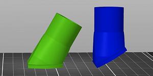
Something else I wanted to quickly report. I went to print the Brass_Drop_Hole_Adapter from version 1.3.5 and the orientation looked pretty strange from what I had printed last time so I went back to the one found in version 1.3.0 and it seems to be correct. See attached picture (1.3.0 left, 1.3.5 right). I think rotating it 30 degrees fixes it in the slicer but just wanted to make you aware.
 Posting Permissions


| BP | Bronze Point | IMR | Improved Military Rifle | PTD | Pointed |
| BR | Bench Rest | M | Magnum | RN | Round Nose |
| BT | Boat Tail | PL | Power-Lokt | SP | Soft Point |
| C | Compressed Charge | PR | Primer | SPCL | Soft Point "Core-Lokt" |
| HP | Hollow Point | PSPCL | Pointed Soft Point "Core Lokt" | C.O.L. | Cartridge Overall Length |
| PSP | Pointed Soft Point | Spz | Spitzer Point | SBT | Spitzer Boat Tail |
| LRN | Lead Round Nose | LWC | Lead Wad Cutter | LSWC | Lead Semi Wad Cutter |
| GC | Gas Check |

 Reply With Quote