The download itself has an images folder that has basically what you are looking for.Originally Posted by SuperMoose


|
   
   
|


|


The download itself has an images folder that has basically what you are looking for.
Ah ha!
Thank you Tyler!
ETA: One other question. On the switch drop tubes, how difficult would it be to modify the STL to put the distance between the openings on the side (for where the screw go) to 9mm center to center? That's what mine measure.
Last edited by SuperMoose; 02-28-2021 at 02:44 PM.
Those were provided by Andar. I do not have the source files for them.
Last edited by TylerR; 02-28-2021 at 05:22 PM.

I�ve used that PWM speed control on my annealing machine, I have a spare that I planned on testing on the bullet feeder.
Sent from my iPhone using Tapatalk
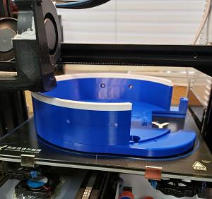
I am experimenting with "pause at level" in cura.....
This will be my "merica" case feeder when it's complete.....
I was worried the change over was going to mess with something..... But it went flawless!


Hi,
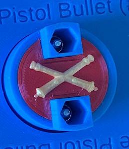
You can also use "Filament Change" script in the same Post Processing Scripts extension, and it works very well. I think the main difference is the Filament Change script sends commands to the printer to pause, then retract the filament, and signal you to feed in the new filament. It's what I used to add the gold cannons to my hub button.
Ed
______________________________________________
Growing old is mandatory, growing up is totally optional!
I do love those buttons Ed. really nice touch.
Actually, I think that is the option I picked.....
Final Product
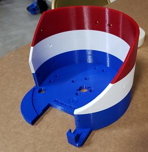
Beautiful!!! That really came out nice...great job!
Ed
______________________________________________
Growing old is mandatory, growing up is totally optional!
Awesome Tyler off to the 3d printer will report back
That is a work of art.
Very great turnout, I can see that being handy in a lot of prints.
I hate asking a question I know has been talked about, but for the life of me, I cannot find where this was discussed. I think there has been discussion about the significance of the size of the wire (thin/thick) in the wiring diagrams. Are the thin wires feeders off of the main wire?? I couldn't find that discussion and want to make sure of getting wired correctly. Any additional insight would be appreciated.
The thinner lines in the diagram would be fine with 24 gauge wire. 18-20 gauge is a good choice for the thicker ones. If you were to describe the diagram in simple terms. Everything can be grounded directly to the incoming 12 volt negative. The relay and the motor are two exceptions. The relay ground in comes from the proximity sensor signal wire. The motor ground comes from the speed controller. Then just follow the flow of the red positive wires and you should be good to go.
Last edited by TylerR; 03-02-2021 at 09:37 PM.
Nice design of the handle GWS, I do like that the plate closes everything off. Couple of good options for folks to choose from.
Looks great GWS. I still have yet to come up with my own thing, so between you and Ed people have some good options to choose from now.
Thanks Tyler, then I take it the positive wire from the sensor goes to the positive IN on the relay? Looks like small red (+) wire gets lost in the diagram on the big red (+) wire running from switch to Relay out +. Is that right?
Sorry to have to have it spelled out so much!
No. And I don't claim to be the best at creating wiring diagrams. Let me try to break it down.
From the 12 volt power source:
-Negative(ground) will go to the switch negative, sensor negative (blue wire), and speed controller negative-in.
-Positive (red) wire will go to the switch positive (outside pin) and that's it.
From the switch:
-Positive out (middle pin) will go to the relay-in positive, relay-out positive, and proximity sensor-in positive (brown wire).
From the proximity sensor:
Sensor wire out (S- black wire) will go to the relay negative-in.
From the relay:
-Negative-out will go to the speed controller positive-in. (This is what confuses people, because its not really a negative current flowing out. It is just a switch that connects positive from the 12 volt source to positive of the speed controller).
From the speed controller.
-Both negative and positive wires connect to the motor. Switching these two wires at the motor will control the direction it turns, CW or CCW
For anyone who wants to understand more about how relays work, this is a decent video. Think of a relay just as a simple switch, but the way that switch gets turned on or off is by applying a low current power source. This way a high load current can be turned on or off using a low current source. The video talks about mechanical relays, but of course we are using a solid state relay. Same concept though.
https://youtu.be/1_YfuH_AcxQ
Thats perfect Tyler. I appreciate you writing it all out. I had a feeling some of those positives were feeders. I am a woodworker trying to learn some of this other "trades" stuff, so the more plain, the better.
 Posting Permissions


| BP | Bronze Point | IMR | Improved Military Rifle | PTD | Pointed |
| BR | Bench Rest | M | Magnum | RN | Round Nose |
| BT | Boat Tail | PL | Power-Lokt | SP | Soft Point |
| C | Compressed Charge | PR | Primer | SPCL | Soft Point "Core-Lokt" |
| HP | Hollow Point | PSPCL | Pointed Soft Point "Core Lokt" | C.O.L. | Cartridge Overall Length |
| PSP | Pointed Soft Point | Spz | Spitzer Point | SBT | Spitzer Boat Tail |
| LRN | Lead Round Nose | LWC | Lead Wad Cutter | LSWC | Lead Semi Wad Cutter |
| GC | Gas Check |

 Reply With Quote