RotoMetals2WidenersTitan ReloadingLee Precision
Snyders JerkyMidSouth Shooters SupplyReloading EverythingLoad Data
Inline Fabrication Repackbox
Page 3 of 5 FirstFirst 12345 LastLast
Results 41 to 60 of 89

Thread: DIY 100 pound pot/master caster

  1. #41
    Boolit Grand Master jmorris's Avatar
    Join Date
    Aug 2007
    Posts
    5,277
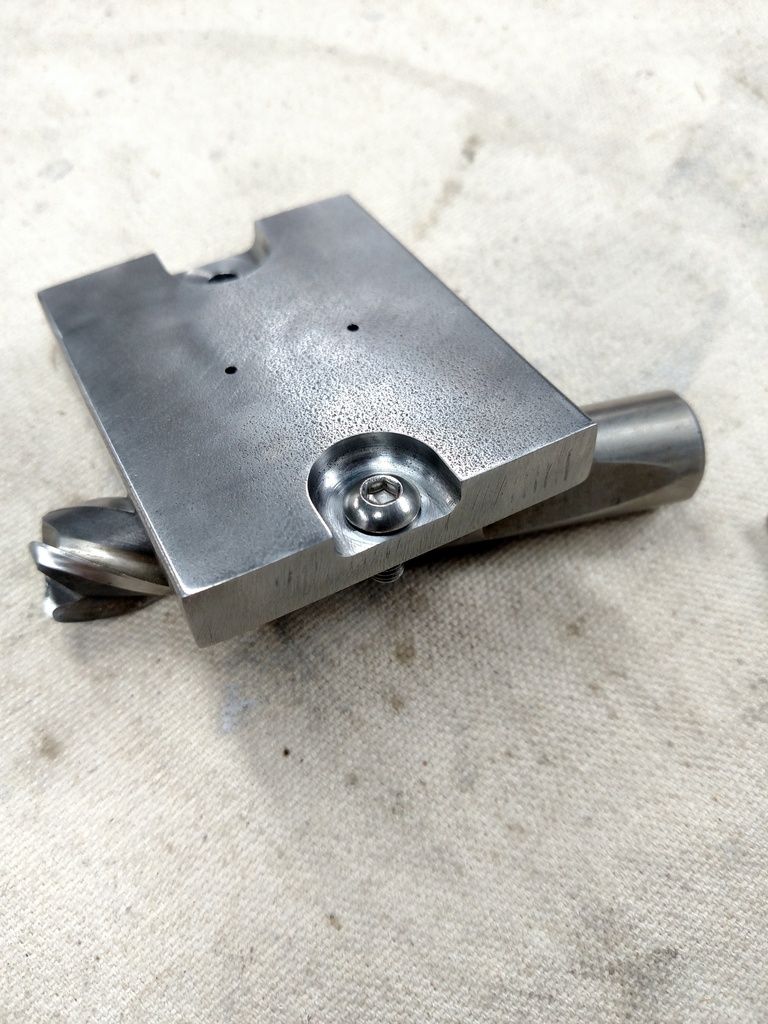
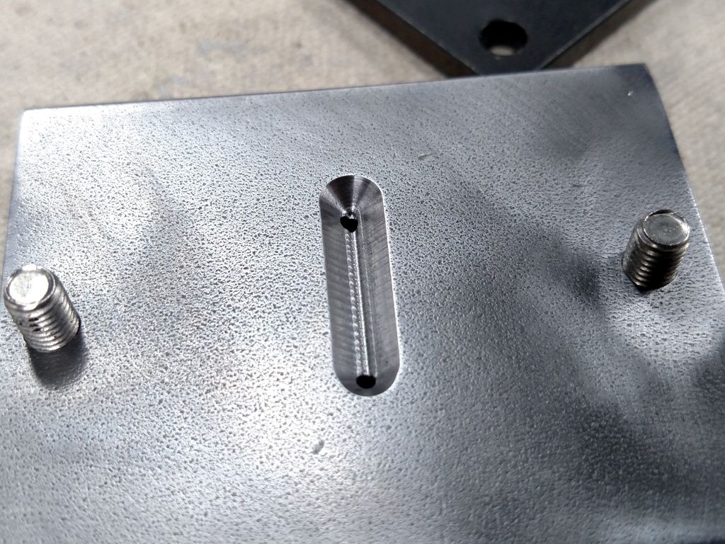
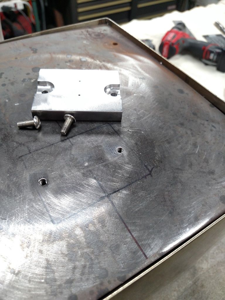
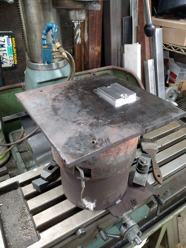
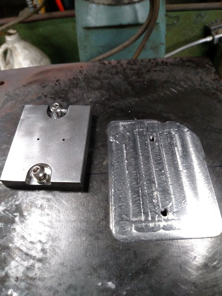
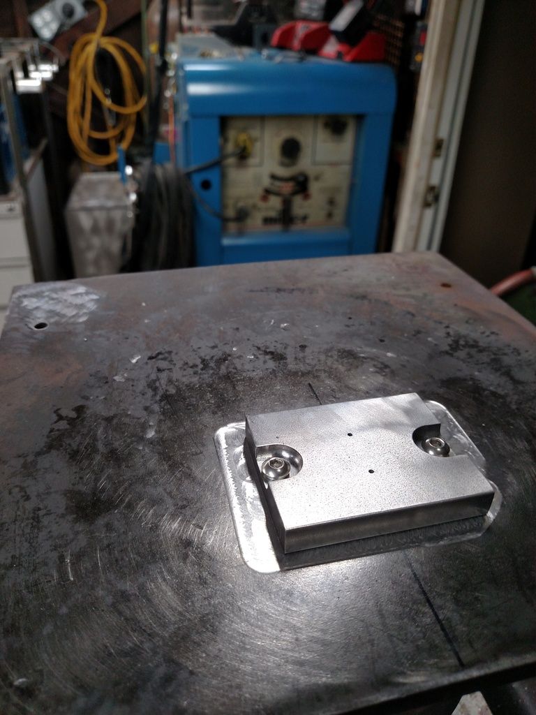
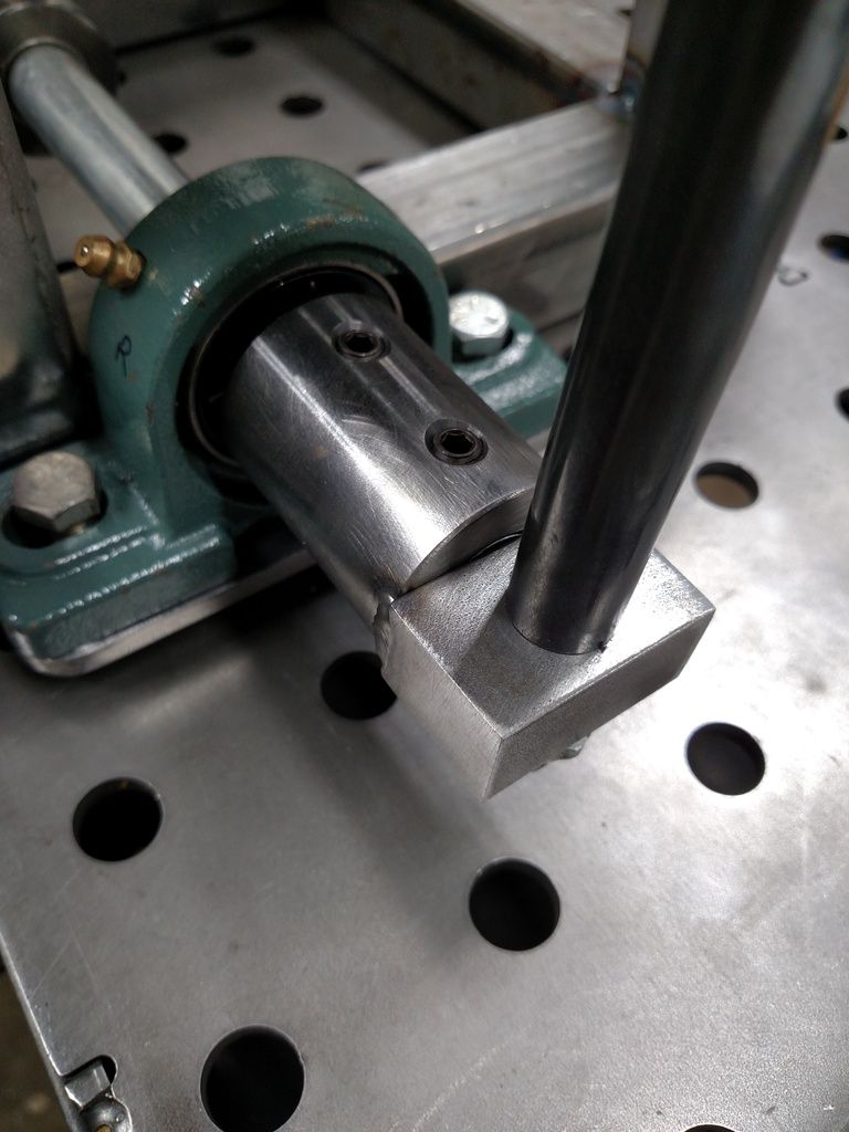
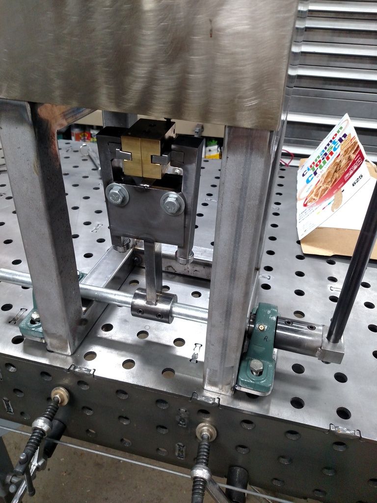
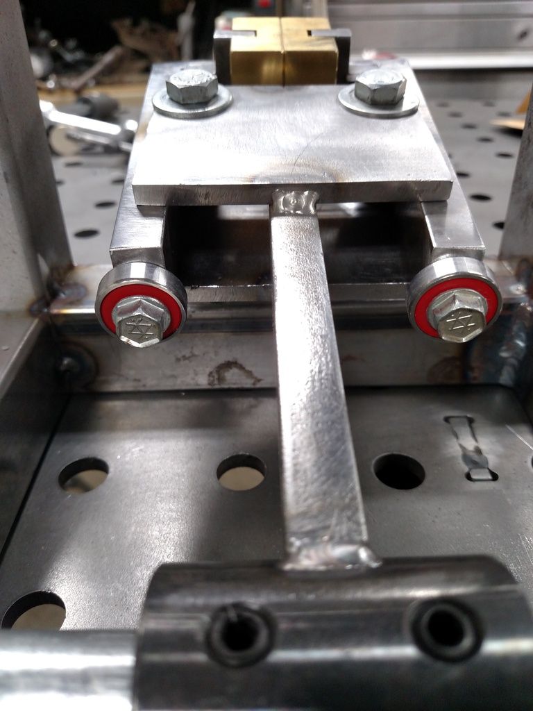
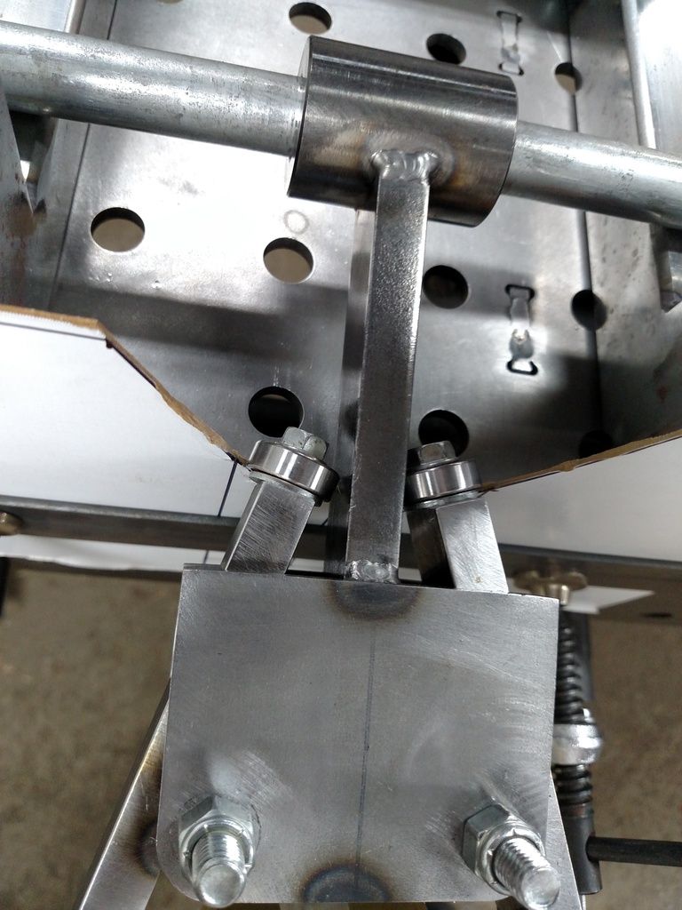
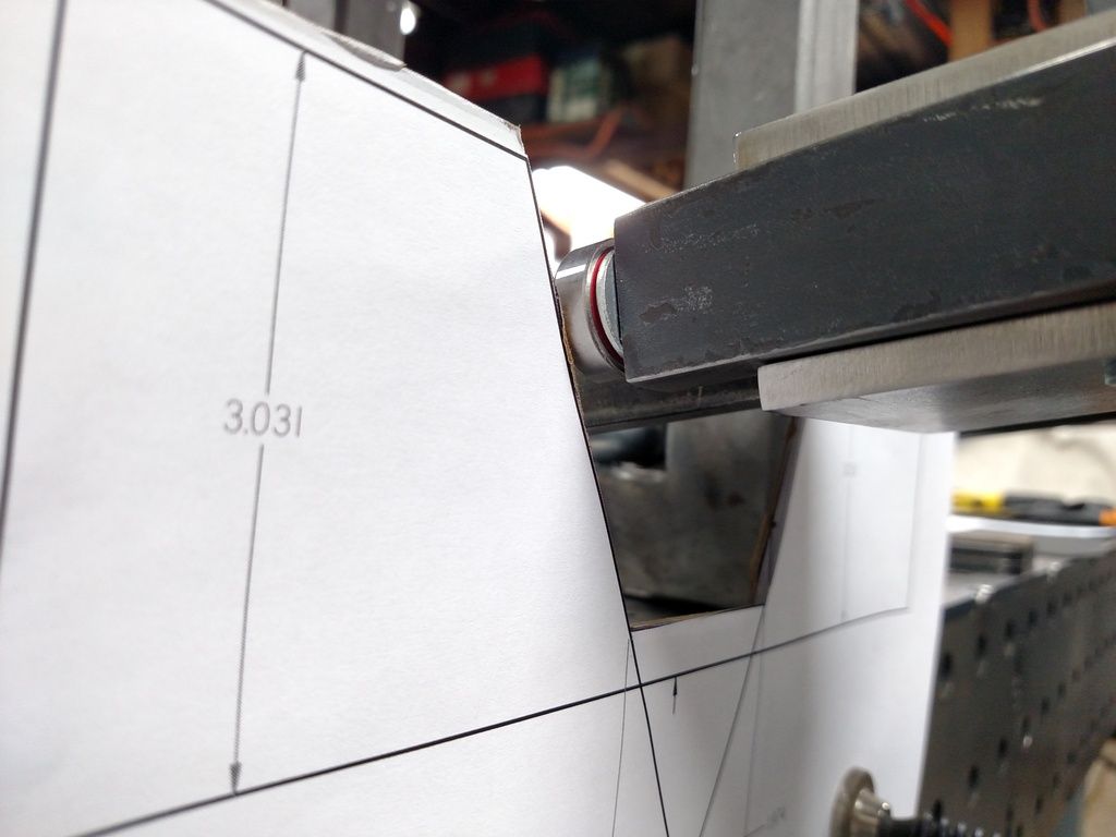
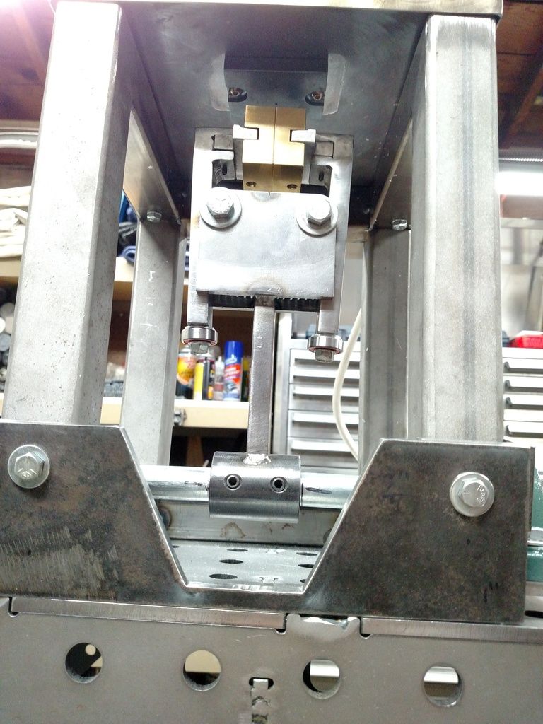
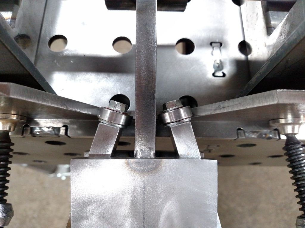
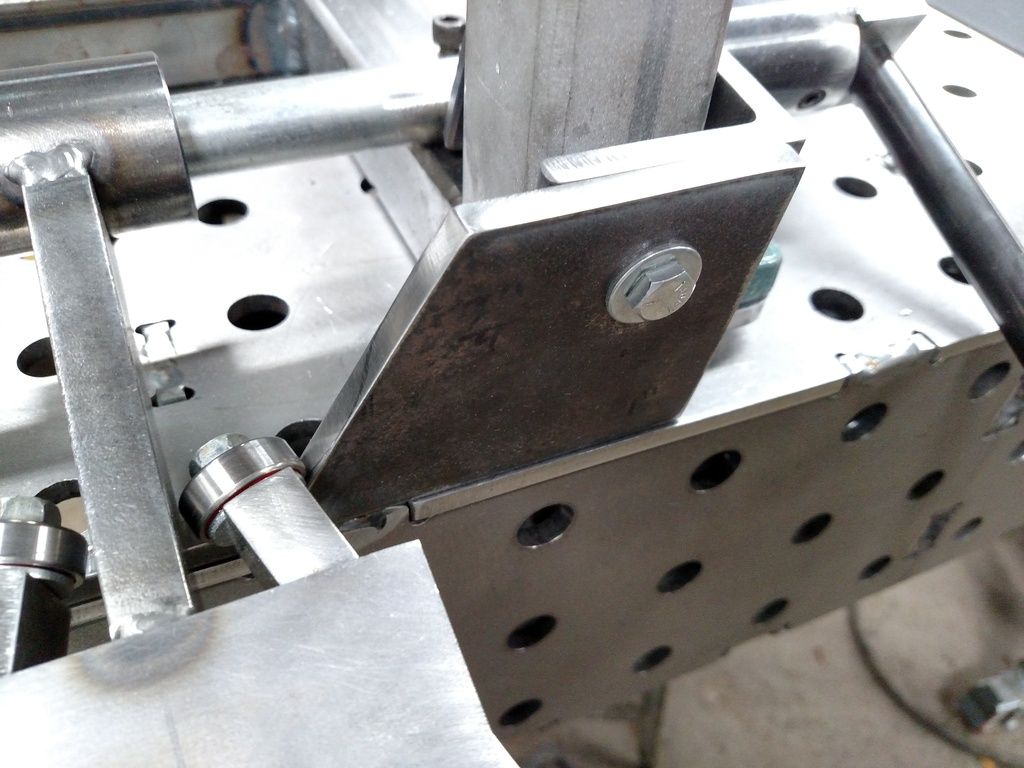
    I machined the slot in the mold carriers I built and while it was in the vise plunged a pocket in the bottom of them where the spring locates. The vertical off the shaft has to have clearance for the spring though.

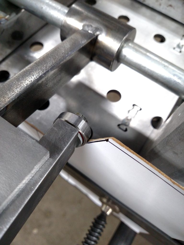
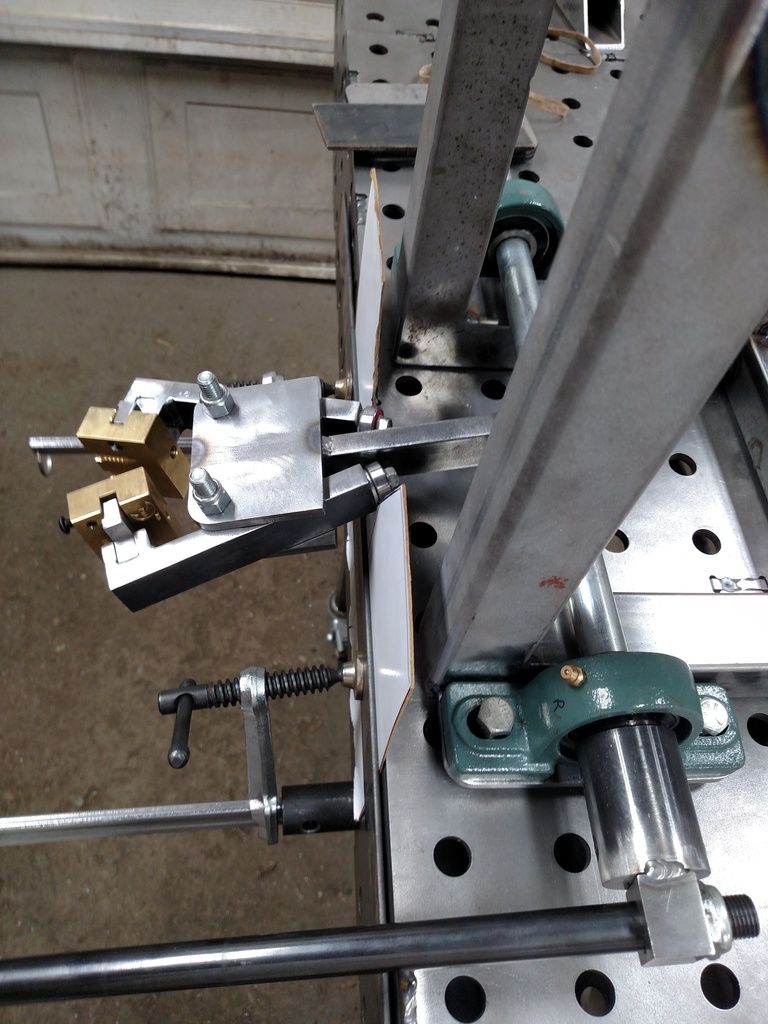
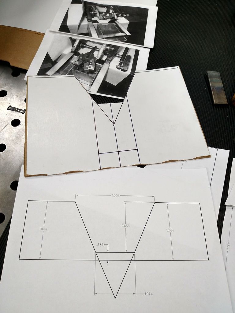
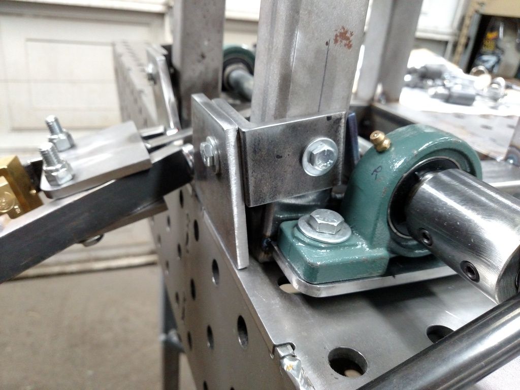
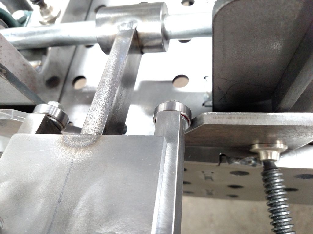
    The drawing is of how I would make them, if I had a "do over" so there is a bearing opposite the mold that rides on the rails. I would use a low profile needle bearing like the blade guide on the left though.
    Attached Thumbnails Attached Thumbnails image.jpg   image.jpg  

  2. #42
    Boolit Master
    Join Date
    Oct 2013
    Location
    Brisbane, Australia
    Posts
    1,775
    Jmorris - how do you think the roller bearings would handle the heat? I'd have guessed they would get a bit too hot and have the grease fry out of them. Nice low friction idea though. I have to keep putting oil on mine nice and smooth.

  3. #43
    Boolit Grand Master jmorris's Avatar
    Join Date
    Aug 2007
    Posts
    5,277
    Jmorris - how do you think the roller bearings would handle the heat?
    I don't really know in that environment. I do know that I have bearings that have held up to a lot more load and heat.

    like the caged needle bearings between wrist pins and a piston or bearings in a turbo for examples.


    Not sure if it really needs to be a bearing to get benefit, a bronze bushing as a roller would be better than steel on steel rubbing. Won't have the oil (coolant/lube) flow like the above examples but also 1000 degrees F cooler and 25,000 or so RPM less rotation.

    It's really not going to be that much more harsh of an environment that the pivot of the arms.
    Last edited by jmorris; 03-26-2017 at 01:15 AM.

  4. #44
    Boolit Master
    Join Date
    Oct 2013
    Location
    Brisbane, Australia
    Posts
    1,775
    Point taken Yet, a turbo does have an oil supply to keep it lubricated. It does amaze me that the oil doesn't catch fire when the turbo is really hot like that, yet i know they don't run like that all the time, only when being really pushed.

  5. #45
    Boolit Grand Master jmorris's Avatar
    Join Date
    Aug 2007
    Posts
    5,277
    Yet, a turbo does have an oil supply to keep it lubricated.
    That same oil will also carry heat away with it too.

    In the application I am talking about it could be a dry bearing really. In its lifetime it wouldn't make as many rotations as a turbo would with one pass down the track and they would have years to take place, not just a few seconds.

  6. #46
    Boolit Master
    Join Date
    Mar 2012
    Location
    SoCal, USA
    Posts
    524
    Nice timing with the suggestions! I still need to mount the springs and hadn't figured it out yet. For now, friction holds them in place.

    This afternoon, I was playing with opening the mold with my hands, and was concerned about how much pressure it would take to open the mold.

    It is time to cut the arm, that holds the mold, down to length. First, it would be a good idea to have a double spout that actually works so I got to work on it. It turns out that the single spout is back further than the center line of my shaft. Oops. I may have to cut the brackets and move the bearings back.

    There was some scrap from making the mold block adapters and it was 3/8" thick. The bandsaw made quick work of getting it to a decent length, then I marked the new spouts and drilled them to 1/16" diameter. No matter how much I cut off, sometimes things are still too short. It is easier to start small and drill bigger if needed.

    The next step was to make a trough for the lead to flow to each spout. It was probably the wrong type of mill, but I grabbed a 3/8" 90 degree v point drilling/slotting mill that I bought for a job. Instead of drilling all the way through and slotting, I just made a little v shaped channel. There was plenty of mist coolant and the feed speed was very slow. I don't even play a machinist on tv.

    In the close up of the trough, you can see that the one spout is not centered in the V. I marked both spouts, clamped the part in the vice and drilled the first hole. When I moved the table to the second hole I was off by about 1/32nd so I bumped the table sideways. Mistake! I debated on just drilling where it landed and should have done that, because I left the part, changed to the mill and ran the trough. It probably won't make any difference, but it was a lesson learned for future work that may be visible.

    My goal was to not have the screws protrude below the spout, so I used a decent size end mill, with a radius, to make pockets for the screws. That mill was sharp and the chips came out like it was aluminum. My dad and brother had bought a bunch of surplus mills by the pound and this was mixed in. It's too bad that place isn't still open, where they got them.

    Drilling and tapping the 3/8" bottom of the pot was fun. I marked the bottom of the pot and then laid the spout on it and just touched the bottom with the same 3/16" drill I used for the through holes for the 10-32 screws. IIRC, a #21 drill was next, but I only drilled to 280 thousandths deep on one and 310 thousandths deep on the other. A standard tap was used to start the holes by hand, then I finished them with an old misc. tap that I ground the tip off, since I didn't have any blind hole taps. It doesn't seem like I got much further with the ground tap. A counter sink was used to clean the holes before tapping and to break the edges of the screw holes on the spout.

    When one hole was tapped, I screwed the spout down and spotted the other hole with the 3/16 drill. It was a tight fit after it was tapped, so I opened the through hole with a 13/64ths bit and that gave me the wiggle room I needed.

    The next challenge is getting the spout to seal to the pot base. The based warped to hell when I tig welded it. Yeah, 400 amps into tig welding a pipe to a 3/8" plate makes things move a bit. So, do I try to machine the pot flat or use something to seal a tiny gap?


  7. #47
    Boolit Grand Master jmorris's Avatar
    Join Date
    Aug 2007
    Posts
    5,277
    That should work. It needs to be fairly flat where they come together but it's not as important as having your valve. Some sand paper of a flat surface should get you there.

    The lead is on its way out the holes once the valve opens.

  8. #48
    Boolit Master
    Join Date
    Mar 2012
    Location
    SoCal, USA
    Posts
    524
    Tonight I decided to tackle the warped base.


    To clamp the pot down, I welded a tab across from the valve mounting plate you see at the front.

    A few light cuts gave me a relatively flat surface.


    It isn't perfect, but I figured the same as above in that hopefully the lead will be more likely to flow out of the two spouts than any small gaps between the plates. The spout is not perfectly flat either. It is all put back together and ready to heat up to see what happens, and if the heat will effect the fit of the two parts.

  9. #49
    Boolit Master
    Join Date
    Oct 2013
    Location
    Brisbane, Australia
    Posts
    1,775
    I don't think the lead will leak out the gaps if it's not perfect, lead is still quite thick, water may leak between the two plates, but lead won't.

    Looks good, i bet you're itching to get it up and running

  10. #50
    Boolit Master
    Join Date
    Mar 2012
    Location
    SoCal, USA
    Posts
    524
    Yes, I'm out of boolits for my 30-30 lever gun and need some 45 acp boolits as well, but I really don't want to change the cord ends on the PID back to 120v and run the lee pot. Also, I have two new NOE molds that haven't been used yet, and they are now 4 months old.

    I should have just saved my 30-30 ammo. Last weekend I only got 18/40 for the Silhouette match. The new mold is a gas check version, so I can up the load a bit and see if that makes any difference.

  11. #51
    Boolit Master
    Join Date
    Mar 2012
    Location
    SoCal, USA
    Posts
    524
    Tiny update:

    This afternoon, I heated up the pot with 2" of liquid lead. The spout didn't leak at all. It dripped just a tiny tad after closing the valve, and left a little tinsel of hot lead hanging off the double spout. After 30 seconds, I could just wipe the drip off...........it was still melted and the spout was hot as a firecracker

    The flow was not great. It seems that opening the size of the hole that the valve sits in would be a good first step. That will allow more lead to the double spout with 1/16" holes. The extra flow/pressure might be enough, if not, I can drill the double spout bigger, by 64ths of an inch, until I get what I need.

    It is still impressive how fast this pot melts lead and recovers when adding more ingots.

    Next step is to mount the arm with the mold and get some rotational action going.

    I had a thought at bright O thirty this morning, when I should have been sleeping. Why can't I use flat plate instead of round stock to guide and close the molds? Bearings should be easier to setup on flat plate and I can mount it just like the round stock so it can be adjusted. I can hand cut plate into an arc or cnc cut it. Heck, the skateboard bearings that the cnc plasma uses would work for this, and we use them in the vacuum motors which power the blow dryers that we repair for our animal grooming customers. They are ABEC 7 grade IIRC, and cheap.

  12. #52
    Boolit Buddy
    Join Date
    Mar 2014
    Location
    North of 49th
    Posts
    173
    Good evening,
    I applaud your efforts......looks well thought out and should work well. When I start working on a long term project, I always like having a "carrot" to keep me going. Now running out of boolits....that's a mighty BIG CARROT!!!
    Keep it up, piles of shiny boolits await you

  13. #53
    Boolit Grand Master jmorris's Avatar
    Join Date
    Aug 2007
    Posts
    5,277
    Why can't I use flat plate instead of round stock to guide and close the molds?
    You can use anything, even nothing if your spring closes the mold tight enough.

    I imagine round was picked to reduce surface area where the two rub together, kind of like ice skates.

  14. #54
    Boolit Master
    Join Date
    Mar 2012
    Location
    SoCal, USA
    Posts
    524
    This machine now has some rotational fortitude!

    Yes, that is a Dillon 550b handle. It sucks compared to the roller aluminum handle, but it was in the scrap bin and was quick and easy to use. A 3/16" drill made a nice pilot hole and I chased it with a 9/16" twist bit, then cut it to length and welded the chunk of steel to the collar/coupler. For now, this allows easy disassembly since only the two set screws hold it tight. Down the road, I may machine some flats on the axle to keep the couplers from spinning and if necessary they will get welded together.


    In this photo, you can see the mold holder also attached to a coupler. I dropped both in the mill vice, with one just as a spacer for the left of the vice, and I made a slot in the other to accept the bar that the mold holder is attached to.

    A fair amount of time was spent going back over the few tack welds that held this stuff together and creating some small beads to withstand use. It works well enough that I wanted to make it more permanent and get the shifting out of the way, that happens when tig welding this stuff. It took a little massaging with 4" grinder and a 60 grit flap wheel and then the 90 degree die grinder with a 3" brown surfacing disc to make the arms work smoothly inside the 1/4" plate sandwich.

    The little pivot tubes are thin, so when I mashed the pedal on the middle notch of the amperage range, the 250 amps of juice left a few tits inside the tube. I hate dremel tools, but use the **** out of my old Cman straight die grinder and the old composite IR angle die grinder. An 1/8" arbor sanding drum, from a dremel kit, fit right in the straight grinder (with a reducer collet) and cleaned up the tits. The nylock nuts on the pivot bolts will get changed to prevailing torque nuts before I run the machine, if I don't forget.


    Did you notice the other little tid bits dangling under the mold holder?


    The two 5/16x18 bolts were left over from something else and were in my add-a-bins. The bearings are 8mm ID and are 608-2rs 8x22x7 mm. I buy these 30-40 at a time, as they are all over the cnc plasma machine and they are the same size that many vacuum motors use, which we repair for customers. I didn't take any photos of drilling and tapping the holes. This time, I used the mill to drill, but tapped by hand in the bench vise.

    A cereal box was the donor for the template for a cam plate. A ruler, square, marker, scissors, and a utility knife made easy work of the prototype. The high tech part comes later.


    That 600 pound fabrication table, that I built, came in real handy. It is only 1/4" plate steel, but it was up to the task of clamping my cardboard template in a vertical position, so I could slide the casting machine around and actuate the arms. Rubber bands were a stand in for the springs and it actually opened and closed the arms.

    Don't mind the ugly weld beads. The batteries are bad in my Miller Elite helmet and I was using the cheap miller AD helmet that came with my 211 (smaller view) and I just wanted to make some progress. The gap I was filling was probably 3 times my filler diameter (1/16" ER-70S6) and it was deep. The boolits won't care how the welds look, on the way to the target.


    Some scrap plates, stacked against the front of the frame, acted as spacers to align the cardboard
    with the bearings.


    I'm pretty sure that Cinnamon Toast Crunch cereal boxes are not military grade and they might turn to toast pretty quick with the amount of heat that 2500 watt element puts into the whole machine. It was time to get more serious.

    1/4" plate seemed like a good material for a cam plate. It works on the Dillon 550b and I was able to make an upgraded plate for my Dillon, so it will run rifle brass through the pistol case feed mechanism. While I had some dirty ways to cut up 1/4" plate, in this garage, none of them were quick and all that precise. What really sucks is when you make a mistake and have to start all over again with whittling down that plate or get out one of the welders and put back what you needed.


    It was time for the high tech approach. This was going to be some work, so that is why I started with cardboard. While I had a whole double, Costco, cereal box to use up, the first quick and dirty template seemed to do the trick.

    CAD is a wonderful tool, but it isn't the easiest program to teach yourself just by doing. This little exercise made me feel old. I had to remember how to use the CAD program since it has been a handful of months since working with it. My drawing and writing skills..........well, they aren't. I wish I would have been able to take CAD in high school or college because it sure beats sketches on a notepad done with pen. There never seems to be enough room on the paper for all the details, then they run into each other and are hard to read. Eventually, it is time to make a new sketch. Just like my papers in HS and college, it is better to edit on the computer and just hit print again. It took two tries to get the dimensions and angles I wanted and I was thrilled with that.


    The print was cut out and laid over the cardboard. It looks like it is close enough and it will look good from my rear-view mirror.

    Since I mentioned it has been months since using the CAD program, you can probably guess it has been the same number of months since using the CNC Plasma Table. It dried up with plenty of plasma dust and drops in the water and needed to be cleaned out. The Santa Ana winds filled that shop with dirt, so the confuser, mouse, keyboard, everything, needed dusted off. When building that table, I thought about having to service it and the muscle it would take to do it. The water tray is light enough for two of us to move without killing ourselves as it is a full 5x10 sheet of 0.090 aluminum. The framework for the slats is aluminum as well and weighs maybe 50 pounds at most. I was able to remove all the steel slats and the remove the frame myself, to clean the table. After scraping and sweeping the trash into a dustpan, I vacuumed the tray and scraped the bottom of the framework.

    It all went back together and I filled the 3 55 gallon drums with air to push the water that was left, into the tray. The garden hose was used to top off the tray. The computer worked and I was able to zero the table. The plasma had to be hung back up on the wall and the torch clamped into the machine, as I had been using it by hand for some other projects.

    Next time around, I will remove the bottom part of the drawing (it was only used to figure out my angles and lengths) and get the cad file into sheetcam where it can write a file for Mach 3 (the machine software) and then it will be ready to cut the part. I didn't do any test cuts today, so hopefully it still gets the job done. The little Miller 375 extreme isn't suited so well to table use. A Hypertherm 65 is on my wish list, with both a machine torch and hand torch. Maybe I will get a video of the part being cut, although many people have probably already seen cnc plasma cutting on youtube at some point.
    Last edited by CGT80; 04-03-2017 at 03:31 AM.

  15. #55
    Boolit Master
    Join Date
    Oct 2013
    Location
    Brisbane, Australia
    Posts
    1,775
    Good to see you have made more progress, nice write up too. I wish i had that bench, would make setup easier than hands that always seem to get welding spatter on them while holding parts in place. That and magnetic clamps that never seem to be strong enough.

    As for the welds you didn't like the look of, there is nothing wrong with them. Yet i do understand frustration when you know you can do better.

    Keep up the good work and of course, PICTURES

  16. #56
    Boolit Master
    Join Date
    Mar 2012
    Location
    SoCal, USA
    Posts
    524
    If pictures are good, does that make video even better?


    Here are some photos of the CNC plasma machine. My dad ordered a bunch of parts for it, over a period of a couple years and I got tired of waiting for him to build it, so I took the lead and got done with his help.

    It will easily hold an 4x8 foot sheet of material. The plasma cutter was a $300 craigslist deal that ended up needing $1300 worth of repairs (that is what they cost new) and I lucked out in only spending $200 on a new front end for the gun and the warranty was still good, to cover the rest. No more used electronic machines for me.


    This is my old AMD 5200+ dual sli computer. It is running XP and is not connected to the internet. I bent the aluminum panel on a homemade DIY bender and then tig welded it and added the hinge and mounted all the electronic gear. The computer station was something I threw together in an attempt to take up as little space as possible.


    Three drums allow compressed air to move the water up the 2" pvc line and into the water tray and have just enough usable volume to fill the table. The table should take 100 gallons or so, but you can't run the water level below the 2" outlets. To drain, just let the air out of the barrels and it all runs back down hill.


    Here is a shot of the pre filter, regulator for the drums, control valve for the drain, and the control valves for the exhaust on the barrels and the air into the barrels.


    That round black thing is the secondary air filter for the plasma cutter, down to 0.01 micron filtration to remove water.


    I still need to get figure out how to get artwork into sheetcam so I can cut more items. We have a business doing sharpening and equipment repair for the grooming industry and may be able to sell cnc cut items through the business. So far, I have only done two images of animals and the rest has been brackets for various other projects.

  17. #57
    Boolit Master
    Join Date
    Mar 2012
    Location
    SoCal, USA
    Posts
    524
    Here is the cam plate for the casting machine:


    This was some scrap that was given to me. The bottom side has a lot of slag and it is not easy to chip off.


    The edge quality is better than some of the past cuts I have made in 1/4" material. It looks like I got my torch square in the holder. Since it isn't a machine torch, it is a bit difficult to get it so that it isn't angled in any one direction.


    It took a bit of thinking to figure out brackets for this cam plate. I wanted to be able to adjust it a bit, in many directions. The urge to just weld it in place was strong. Right now, these plates just have 1/4" through holes, but I can slot them later to get some adjustment.


    The brackets are just some 2" angle iron from the scrap pile.


    The bearings don't engage the first part of the plate, but they hit evenly/at the same time. This picture is from when I was mocking up the plate to figure out how to make brackets. You can see the scraps acting as spacers.


    The center arm bottoms out on the plate, before the bearings touch the arm. This will allow me to tap the arm to shake boolits free. The thought crossed my mind, to grind the plate to allow the bearings to make more contact with it. Bearings are cheap and this machine is just for personal use..........they should hold up fine.

    The springs to actuate the arms are here, but you can't see them......
    They are pushed up between the 1/4" front and back plates. This reduced the pressure needed to activate them and it allows the arms to open all the way. The compressed height of the springs is too much to allow full opening. For now, I will try it as is.


    Now that the machine has a stop for the downward motion, it needed a stop for the upward motion so the spout would line up. A little tab and a bolt did the trick.


    My hardware collection is almost all national coarse thread, so I didn't get to use a fine thread bolt for more precision. This is 1/4"x20 tpi. I was going to tap that hole, but I couldn't get my little drill in there or a tap handle. Instead, I drilled at an angle with a 3/16" bit and then opened it up with an old step bit, at and angle, and finished it off with a 60 degree chamfer bit, which was short enough to get at with the drill vertical.


    It is nice to see the project almost to a usable point. It could be used, but I would have to knock the sprue plate by hand. Next up is to figure out the sprue plate activation and decide if I need anything to push the mold halves closes. Gravity is a pain and it lets the halves droop a bit, so they have to be closed quickly to mate evenly. This mold is more temperamental than the 40 cal NOE brass. If needed, I can add a spot weld to the mold adapter so they can't droop as much.

    Maybe next weekend, I will get it ready to run. This week, I have work, gun club meetings, and a catectomy to do on my friend's Harley exhaust header.

    Thanks for viewing.

    Keep your stick on the ice...........oh wait, I'm not that Youtuber!

  18. #58
    Boolit Master
    Join Date
    Oct 2013
    Location
    Brisbane, Australia
    Posts
    1,775
    Yep a video is far better than pictures

    I love the idea of the water in the drums being displaced with compressed air, so simple and a way to keep the table "dry" when not in use.

    hehe shame you aren't THAT youtuber, he is quite entertaining. Love to have a chat with him, see if he is just like that in real life.

  19. #59
    Boolit Grand Master jmorris's Avatar
    Join Date
    Aug 2007
    Posts
    5,277
    This is my old AMD 5200+ dual sli computer. It is running XP and is not connected to the internet.
    If you don't let them get "infected" it doesn't take much computing power to run a CNC plasma, mine is still running on the 286 I started with.

    If I am just making a single part or even a few parts, a lot of times it's faster to just use my pantograph with a plastic template vs CAD and setup to CNC the part.


  20. #60
    Boolit Master
    Join Date
    Oct 2013
    Location
    Brisbane, Australia
    Posts
    1,775
    286? wow, that is an old setup. I never owned one, my first was an XT, then a 386, shows my age

    Does your cad software run on DOS? I guess we are spoilt with modern day fancy GUI interfaces to design things.

Page 3 of 5 FirstFirst 12345 LastLast

Posting Permissions

  • You may not post new threads
  • You may not post replies
  • You may not post attachments
  • You may not edit your posts
  •  
Abbreviations used in Reloading

BP Bronze Point IMR Improved Military Rifle PTD Pointed
BR Bench Rest M Magnum RN Round Nose
BT Boat Tail PL Power-Lokt SP Soft Point
C Compressed Charge PR Primer SPCL Soft Point "Core-Lokt"
HP Hollow Point PSPCL Pointed Soft Point "Core Lokt" C.O.L. Cartridge Overall Length
PSP Pointed Soft Point Spz Spitzer Point SBT Spitzer Boat Tail
LRN Lead Round Nose LWC Lead Wad Cutter LSWC Lead Semi Wad Cutter
GC Gas Check