I am making a case collator. And I want to put 2 micro-switches in the feed tube. But I am unsure how to wire the switches. I have a hard time comprehending electrical skamaticks (sp), but if I see a picture I can understand that. Kevin

|
   
   
|


|


I am making a case collator. And I want to put 2 micro-switches in the feed tube. But I am unsure how to wire the switches. I have a hard time comprehending electrical skamaticks (sp), but if I see a picture I can understand that. Kevin


Join the club! I don't even try.
Wayne the Shrink
There is no 'right' that requires me to work for you or you to work for me!


terminal post ►*\ *◄other terminal post
For a switch you cut the hot lead in half and hook the ends to the terminal posts. In the crude sketch the switch is open and when it's closed that \ in the middle connects the 2 posts together and current can flow thru. I'd imagine a micro switch is the same principle.
Mike
Benefactor Member NRA
Life Member Iowa Firearms Coalition
US Army Vet
There are two ways to conquer and enslave a nation.
One is by the sword. The other is by debt.�
John Adams 1826
Think of it like plumbing, same thing only different. Switch is a shutoff valve.
I am going to assume that you want a start switch (lower), and a stop switch in the upper position. In this case you would want to wire the switches in series, hot line to one side of the start switch, then a jumper from the other side of the start switch to one side of the stop switch, then one wire from the other side of the stop switch to the motor.
you really could get by with just one (normally closed) switch at the top of the drop tube to control the amount of brass in the tube. (By normally closed I mean that when the brass in the tube activates the micro switch the contacts in the switch open and turns the current to the motor off.)


Well, If you are unsure of connections and it's a standard SPDT micro switch, it's a 50-50 thing.
make connections to C. and N.O.
and if the function is opposite of what you want,
connect to C. and N.C.
~~~~~~~~~~~~~~
�If someone has a gun and is trying to kill you, it would be reasonable to shoot back with your own gun.�
― The Dalai Lama, Seattle Times, May 2001

Like JonB mentioned, normally micro switches have a "common" a "normally open" and a "normally closed" terminal (but there are switches, not as common as the 3 terminal, that only have two and the switch is "off" until activated). So the switch (or tool, machine) can be "on" all the time and "off" when activated or the opposite, "off" all the time and "on" when activated. For a good answer to your question we need more info; what you want to happen when...
My Anchor is holding fast!

If you switches are not marked NO C NC (all quality switches are marked), get out your trusty $7.95 (or FREE) HF DV meter and check continuity (resistance/ohms). Everybody should have one of those cheap HF red meters. They give them away. I have 10 of them.
That way, you can see which contacts are normally open and normally closed and wire accordingly.
......like falling off a log.......
banger

If your plan is for two micro switches, then I need more info on what the switches do before I could tell you how to wire them. They can't both be "off" switches breaking the hot, as once the first is open, it all stops, and nothing else happens. If your switches perform multiple signal functions, or operate solenoids, etc, then you'll need a contactor, or relay to perform the function, and not turn off power to your collator.
Post more info on how the collator functions, and what each switch does so I can determine the circuitry to make it work. Been retired for 5 years, butpretty sure I can still draw you a start/stop, signal circuit.
A micro switch wont work as a "start" switch, unless something mechanically trips that switch to start a function. It's all sitting there static to begin, so without some form of manual off/on switch to start, it wont begin the sequence.
I am sorry on my time delay. Life gets in the way sometimes.
I made a couple drawings of how i want to place the 2 switchs between the case source (a pail above the press) and the loading press (the destination of the cases)
The lower switch will start the motor when case quantity gets low, and the upper switch will stop the motor when the quantity of cases fills the tube.
I haven't purchased any switches yet. So I don't know what wiring they will have.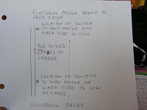
All quality industral-grade Micro-Switches (a trade name just like Kleenex means facial tissues) will be exactly the same. NO / C / NC. 3 screw or HECO terminals labeled as such. What varies is the travel distance, actuation mechanism attached, rating, etc.
Some have just a button sticking out you press on. Some have a long finger that actuates the button. I even have several that have a roller (spring loaded) attached to the button to roll over a cam to actuate.
Actuation choices are almost limitless. The standard connection configuration is usually not.
Lower switch turns on motor when weight (my assumption) is low so it's normal open/button pressed - starts motor when button not depressed. Upper is normal closed - stops motor when button pressed. You have to watch the force/over-travel on microswitches - too much will break them - i.e. put a mechanical stop behind them.
Whatever!
That wont work, as once the top switch opens the circuit, the bottom will have no power, so it wont start when it gets low again. What is required is a relay to start and stop the motor. In this manner both switches will have power all the time, but the relay will be pulled in or dropped out by each switch. The upper switch in the holding circuit, which is a maintained NC switch that breaks the holding circuit when opened. The lower start switch needs to be a momentary NO switch which closes the start circuit, and the relay is held in by the closed circuit contacts in the relay.Originally Posted by popper

Here's a simple start-stop circuit for any motor. The start and stop pushbuttons would be replaced by the start and stop limit switches.
http://www.otherpower.com/images/sci...2819/3Wire.jpg
I would get rid of the lower switch and use a Micro-Switch with it hooked to the normally closed side and simplify the wiring. Tube fills case pushes the arm down opens the circuit kills the power, pull lever case feeder feeds another case.
45 ACP because shooting more than once is just silly!!
Democracy is two wolves and a lamb voting on what to have for lunch. Liberty is a well-armed lamb contesting the vote.
Gave myself a headache trying to explain the circuit, mebbe Ill try later.
OK try again. Power to both C terminals of switches. Both switches NC terminal to motor/relay. Tube empty; power from bottom switch to motor. Tube filling, no power from bottom switch to motor, but power from top switch. Tube fills, top switch opens, no power to motor. Simple as I can explain (figger?).
It gets muddier and muddier...
Last edited by mdi; 07-02-2016 at 02:35 PM.
My Anchor is holding fast!
Wow I am even worse than inept, my eyes glazed over the posters above trying to assist you. I understand basic electrical circuits from high school...but the breadboard was as far as we got.
I can't quite understand your drawing, but it looks to me like you need to have a split line wire
not running line side threw bottom switch to upper. If I understand what you are trying to do.
Keep in mind switch only is on line side, neutral & case grd. have nothing to do with switch.
The upper switch will only be energized, with lower closed the way you have it. So the line wire
to bottom switch, needs jumper to line side of upper switch. Each switch having load wire to motor, and common neutral & case grd. returns from motors.
I understand the drawing but I don't know why you would make such a simple task so much more involved and difficult to accomplish? I must have missed something?
45 ACP because shooting more than once is just silly!!
Democracy is two wolves and a lamb voting on what to have for lunch. Liberty is a well-armed lamb contesting the vote.
My explanation is basically the same as Drm550's. I don't think it gets any simpler to use two switches to turn a motor on and off. You could always plug the motor in the wall when you want it on and yank it out when you want it off...
My Anchor is holding fast!
Haha you found my method...except I use a surge protector for the on off switch.
 Posting Permissions


| BP | Bronze Point | IMR | Improved Military Rifle | PTD | Pointed |
| BR | Bench Rest | M | Magnum | RN | Round Nose |
| BT | Boat Tail | PL | Power-Lokt | SP | Soft Point |
| C | Compressed Charge | PR | Primer | SPCL | Soft Point "Core-Lokt" |
| HP | Hollow Point | PSPCL | Pointed Soft Point "Core Lokt" | C.O.L. | Cartridge Overall Length |
| PSP | Pointed Soft Point | Spz | Spitzer Point | SBT | Spitzer Boat Tail |
| LRN | Lead Round Nose | LWC | Lead Wad Cutter | LSWC | Lead Semi Wad Cutter |
| GC | Gas Check |

 Reply With Quote