Reloading EverythingRotoMetals2Titan ReloadingSnyders Jerky
RepackboxLee PrecisionInline FabricationMidSouth Shooters Supply
Wideners Load Data
Page 4 of 5 FirstFirst 12345 LastLast
Results 61 to 80 of 100

Thread: Automated Master Caster and Star run report

  1. #61
    Boolit Master
    Join Date
    Oct 2013
    Location
    Brisbane, Australia
    Posts
    1,775
    A double acting cylinder stands more chance of being fully closed yes. With limit switches it has to be all the way back to engage the switch too, so either it is all the way back or very close to it.

    I find that the spring in my cylinder and gas strut isn't always quite strong enough to pull my mold all the way back of i have a stuck projectile in the mold. The sprue cutter drags on the slight bump and will not always reset, the system cycles again to try and clear it though. A double acting cylinder would pull it back into position more reliably but use more air to do so.

  2. #62
    ADMIN


    HATCH's Avatar
    Join Date
    Sep 2008
    Location
    Lexington, SC
    Posts
    6,707
    The problem with the Wyman pneumatic setup is the air cylinder for movement is spring return.
    You have to use a additional spring because the spring in the cylinder isn't strong enough.

    You will get failures because either the additional spring fails (fatigue or hot lead dropped on it) or when the mold heats up the sprue doesn't close all the way so the machine doesn't hit the limit switch to start the next cycle.

    We (Wyman and myself) have discussed switching over to a double acting cylinder.
    This would require a total rewrite of the program in order to deal with the power closed.
    For those that don't use the "double tap" feature then the changes to the software would be very basic.
    The "double tap" section would be a total rewrite because we have to factor in the power close feature.
    It isn't impossible but it will take some thought to make it operate like it is now.
    You can also just replace the air valve with the same one used on the star setup and it will work without a program change.
    But you will lose the manual operation of the machine.

    Right now I am about 1/2 way done with a two timer setup program. It basically will allow you to run two different sets of times.
    In this case its standard bullet (less the 250 grains) vs large bullet (500grains).
    You have a switch that will allow you to pick whichever time you need to use.
    I don't cast anything larger then 300 grain.
    So for me what I will do is optimize one of the time settings for smaller boolits (125 grain) and setup the other timer setting for larger 200 grain boolits.
    This will allow for higher production rates on the smaller ones and correct cool down times for the larger grain ones.
    There is an additional change to the hardware side to handle the larger grain boolits.
    Right now the timer is controlled by a 250K ohm pot. I would say that its good for up to about a 300 maybe 350 grain boolit. It isn't large enough.
    So I will wire a resistor in the switch so when you turn on the large grain boolit feature, you also would change the resistance in the pot from 0 to 250K to 250K to 500K.
    This would allow larger boolits to be dropped without affecting the fine tuning of the smaller pot.
    Example would be a speedometer that goes 0 to 120 mph. the steps are 10mph. Well if you doubled the speedo but didn't change the arch (ie its only a 180 arch) then the steps are now 20mph instead of 10mph.


    Now onto the Tappers.
    I researched more into this.
    They are electric and they are solenoids.
    They are shown here in this video -> https://www.youtube.com/watch?v=B0TWNmgEMnM
    If you read the comments he says "
    The shaker's are build from an electric magnet."
    His native language is German so I would assume he meant that they are solenoids.
    Looks like he uses pull type and has a spring to push it back out with some force.
    He made a piece that fits over the shaft of the solenoid.
    Look at this video he made and it shows a better picture of the solenoid. ->
    https://www.youtube.com/watch?v=tb9Kfz3Q9q8


    Don't like being hammered by the Cast Boolits Staff, then don't be a nail.
    The rules are simple to follow.

  3. #63
    Boolit Master
    Join Date
    Oct 2013
    Location
    Brisbane, Australia
    Posts
    1,775
    I'm considering modifying my cylinder to make it double acting, the air solenoids i have are double acting, i have just plugged one port of them off. I think my gas strut may be wearing out, it has done ok, i have going on 30,000 projectiles with that strut. Over time i'm sure there will be refinements that will be made. One of which will hopefully be mold tappers.

    I got a few 12v 1A solenoids off ebay for the idea of using them as tappers. They are spring loaded so as you turn them off and on, the rod on the end can strike the mold. The problem was that they didn't have enough force to do much, they would need to be a higher wattage it seems.

    With the removal of the return spring from the cylinder, it should give me the extra room required to install a bigger piston to take the new seals and still have the required cylinder stroke.

    I'd like to have pre-set times worked out to maximize production. But i'd suspect this would change with ambient temperature as well, so you will always have to do fine tuning.

  4. #64
    ADMIN


    HATCH's Avatar
    Join Date
    Sep 2008
    Location
    Lexington, SC
    Posts
    6,707
    Make some end pieces for the tappers so there is a little weight.
    When it comes to ambient temperature you will find that you can have a general setting for year around use provided that you don't cast outdoors in freezing weather....
    Don't like being hammered by the Cast Boolits Staff, then don't be a nail.
    The rules are simple to follow.

  5. #65
    Boolit Master
    Join Date
    Oct 2013
    Location
    Brisbane, Australia
    Posts
    1,775
    I was going to use brass or aluminium as to not damage the mold where they struck, essentially have a wear item that can be replaced as needed. A little extra weight isn't a bad idea, i just don't know how much energy i could get as the stroke was quite short, so not much time to gain a lot of inertia, but it may be just enough. I have found that most of them do just fall out, but it is not 100% reliable that they will both fall. Even with using an oxy torch as Jmorris does to put a coat of carbon on them to help with releasing them.

    That is essentially what i was thinking too. Have a good mid point that you set it to, then adjust it from there. It never gets below freezing here, a few degrees above freezing is the lowest we get in mid winter. Summer can get up to 40C, sometimes a little more, the times you wish you never left the AC.

  6. #66
    ADMIN


    HATCH's Avatar
    Join Date
    Sep 2008
    Location
    Lexington, SC
    Posts
    6,707
    To be honest I cast in temps that range from 60 to 100 and use the same set of times with no issues.
    Don't like being hammered by the Cast Boolits Staff, then don't be a nail.
    The rules are simple to follow.

  7. #67
    Boolit Mold
    Join Date
    Dec 2011
    Location
    Onida Sd
    Posts
    13
    I use a long spring attached where the original handle was. It is hooked to a mount on my stand behind the caster and runs about horizontal when the handle is up. It elimantes the lead spill problem ruining your spring and is heavier for a more positive return

  8. #68
    Boolit Master
    Join Date
    Oct 2013
    Location
    Brisbane, Australia
    Posts
    1,775
    I have found if i try and go too fast, i get a lead smear under the sprue plate that hangs things up some times. I don't know if i'm just not letting it cool enough, or it may just be the nature of the beast, and over time it builds up no matter what.

    I have found i have not needed to change my times between winter and now being spring, it has warmed up a fair bit.

  9. #69
    ADMIN


    HATCH's Avatar
    Join Date
    Sep 2008
    Location
    Lexington, SC
    Posts
    6,707
    You need more time at the top after lead pour if you are getting lead smears.
    Don't like being hammered by the Cast Boolits Staff, then don't be a nail.
    The rules are simple to follow.

  10. #70
    Boolit Master
    Join Date
    Oct 2013
    Location
    Brisbane, Australia
    Posts
    1,775
    That's what i thought too. More time to cool and the lead will be more solidified before being cut off. I'll just need to find it's happy setting and work from there.

    Not a bad idea sdharley. I have actually removed my handle so i could mount other things to the shaft. But it does keep it away from lead splashes.

  11. #71
    Cast Boolits Owner


    No_1's Avatar
    Join Date
    Mar 2005
    Location
    N.E. Florida
    Posts
    12,607
    Quote Originally Posted by HATCH View Post
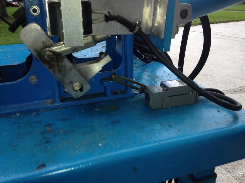
    Only problem with your setup is that the machine doesn't know where the mold is at any given point. It assumes based on time that the mold is at the top (or bottom) but has no clue. I would try and figure out how to add a limit switch to the top position and then set it to run one cycle.

    Right now the Wyman/hatch design is set for one cycle based on the limit switch.
    The limit switch closes then the timers start. After it runs the cycle it stops until the limit switch is closed again. So of a boolit is stuck in the mold and causes it to be stuck at the bottom it doesn't keep running.

    And as far as adding a PLC, it would be easy to add it to your design even with hydraulics and electronic lead pour control
    You are correct Charles however it would be an easy fix for me since I already have this switch which prevents the lead from pouring unless the mold is under the spout. I believe I can use this switch as a start cycle signal switch to the timers.


    Quote Originally Posted by Tazza View Post
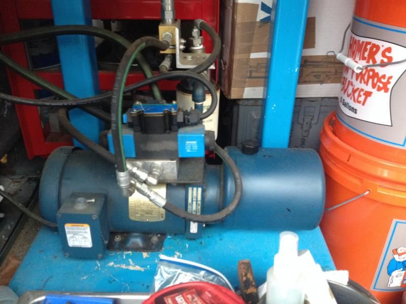
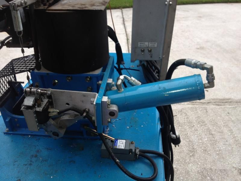
    I liked the hydraulic double acting cylinder design, but i was too concerned with making mine run that way. With hydraulics, you stand far more chances of damage if something was to hang up. Most of the pumps generate around 2,000 PSI of pressure, but you can install a relief to drop that down. Hoh did you manage the heat the pump generated, did it need an oil cooler?

    Hydraulics are far smoother than air, as it is not compressible. You the tight point where you cut the sprue, it is nice and smooth.

    The simplicity of timers is great though, a lot fewer points that it can fail. The limit switches are really good as it will not move further without it knowing where the mold is.
    I have had no problems with hydraulics set up. The pump puts out 3000 PSI and the pressure relief keeps it at a more manageable level. I was worried about the fluid temp since the system runs against the relief constantly but a quick temperature check revealed a average of 160 degrees. It is a bit noisy....

    Quote Originally Posted by Tazza View Post
    A double acting cylinder stands more chance of being fully closed yes. With limit switches it has to be all the way back to engage the switch too, so either it is all the way back or very close to it.
    The double acting cylinder is the only way to go.


    Although I like the idea of going the PLC control I like the ability to adjust the multi-timer set up instantly with no special tools. The addition of the control screen with remedy the need for a PC to change the program.
    "The only way to deal with an unfree world is to become so absolutely free that your very existence is an act of rebellion."
    - Albert Camus -

  12. #72
    Boolit Master
    Join Date
    Oct 2013
    Location
    Brisbane, Australia
    Posts
    1,775
    The high pitched whine does make them less enjoyable, especially when running for long periods of time.

    The switch you have in place for the lead pour could be used as a limit switch, i'd like to have one that activated when the mold is fully down too.

    Did you modify the ram or set it is fully extended and retracted every stroke as to not put extra force on the MC frame? Or did you just wind the pressure right down to do this? I work on hydraulic gear in my spare time and know just how much force a hydraulic ram, even a small one has. I built an argon transfer pump that was powered by a hydraulic ram, i underestimated for force it could apply, and it tore welds off the support brackets.

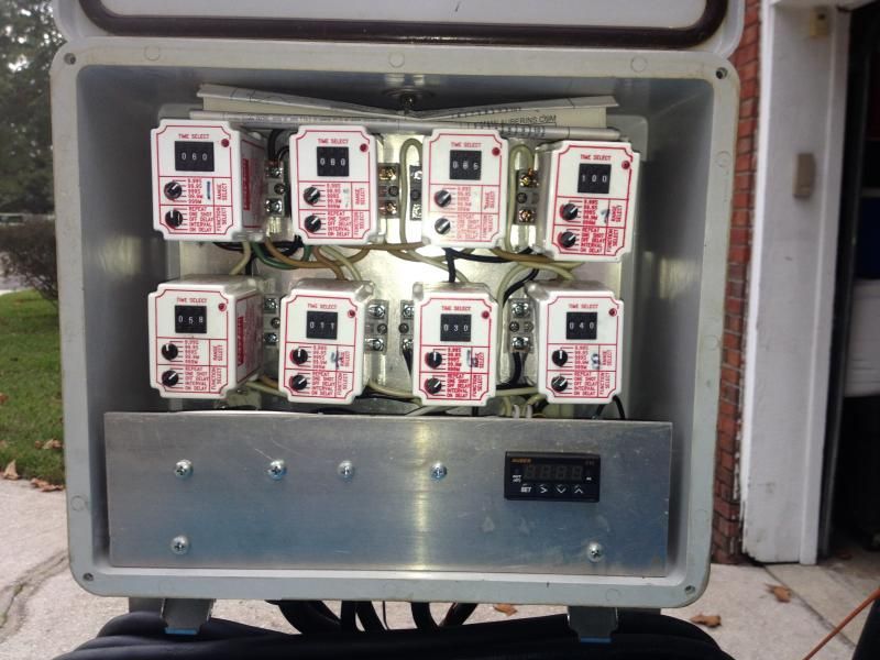
    Your setup is great that you can adjust on the fly, no coding to alter for any delay you want, yet the timing relays for most of us are very expensive. Hatch was talking $80 or so each, and you needed quite a few of them to do the job.

  13. #73
    ADMIN


    HATCH's Avatar
    Join Date
    Sep 2008
    Location
    Lexington, SC
    Posts
    6,707
    Yes the limit switch I gave you for your lead pour safety would work fine. I think it only has a single set of contacts so you would need to use a relay if you wanted to keep the lead pour safety.

    The problem with relays is the cost and amount of wiring needed. My cost on the relays you used is @$150 each or was several years ago when I looked them up.
    So that would put the cost on relays alone at $1200. Factor in another $150 for a enclosure and small parts. That's a pile of money that most people wouldn't want to spend.
    The PLC setup doesn't allow for on the fly adjustments without the use of a expensive display or hooking it up to a PC, however the PLC can do the functions of a 100 relays or more.
    Prime example is that the current PLC program uses less then 1% of the available program space.

    I was able to duplicate the basic automation functions using just 3 relays. It runs fine but doesn't have a double tap feature. It allows you to control the three basic functions. Top timer (lead cool), lead pour amount and bottom timer (mold cool).
    It runs off a limit switch and will run only one cycle per limit switch closure.

    I am not saying that any design is better then any other design. What I am saying is there are different ways to do it and with each way there are limitations.

    Switching over to a double acting cylinder on the Wyman design would solve the only problem that I have come across. Which is the sprue plate not closing 100% sometimes.
    Don't like being hammered by the Cast Boolits Staff, then don't be a nail.
    The rules are simple to follow.

  14. #74
    ADMIN


    HATCH's Avatar
    Join Date
    Sep 2008
    Location
    Lexington, SC
    Posts
    6,707
    BTW impressed that you have a set a prints. My prints are in my head.
    Don't like being hammered by the Cast Boolits Staff, then don't be a nail.
    The rules are simple to follow.

  15. #75
    Boolit Master
    Join Date
    Oct 2013
    Location
    Brisbane, Australia
    Posts
    1,775
    That sure is a big chunk of cash to spend on timing relays when a computer based setup costs less than one of them. Great if you get them for free, not so much if you need to buy them....

    The control box that Kayak1 came up with allows for on the fly adjustments of everything, this is what i am using. The issue seems to be that the Arduino is very susceptible to noise on the power lines, unlike the Click PLC you are using. The arduino that it uses costs about $12, display about $14, a few other components adds up to under $40.

    Does the Click PLC have analogue inputs that you can use to adjust times by altering the voltage being fed into it? or does it only have digital outputs? on/off?

  16. #76
    ADMIN


    HATCH's Avatar
    Join Date
    Sep 2008
    Location
    Lexington, SC
    Posts
    6,707
    Sorry I was typing when you were responding....

    The ideal setup is to have a limit switch at the top and at the bottom.
    That way the machine always knows where the mold is.

    To be able to have it adjust the timers automatically based on the lead pour input. Sorta have a sliding chart the would increase the timers based on the size of the boolit.

    This can all be done with a PLC but would require a additional input block to handle to potentiometer input (I think is like $150) and would require some fancy programming.
    I am not sure if the PLC we currently use can do it.
    I do know that the PLC we use at work can do it but its meant for DDC and its not available to everyone. Not to mention it requires special software.

    I almost used that PLC (ZN551) but didn't because of the fact no one could duplicate it because they didn't have access to it.
    Heck there is even a display that would allow you to change the timers in it but again no one else could duplicate it.
    Don't like being hammered by the Cast Boolits Staff, then don't be a nail.
    The rules are simple to follow.

  17. #77
    Boolit Master
    Join Date
    Oct 2013
    Location
    Brisbane, Australia
    Posts
    1,775
    That would be the ultimate setup. It makes sense too, the more lead being dropped means more heat to dissipate, so the sliding scale would work well.. another member had the idea of having temperature senders on the molds to make it so it knew when to dump. That would give the ultimate speed possible and would adjust for ambient temperature changes. But just how fancy do we all need it to be.

    You sure have nice toys at work. Shame we couldn't justify the cost of some of it

  18. #78
    ADMIN


    HATCH's Avatar
    Join Date
    Sep 2008
    Location
    Lexington, SC
    Posts
    6,707
    I am gonna figure out a display but its not priority right now.
    Don't like being hammered by the Cast Boolits Staff, then don't be a nail.
    The rules are simple to follow.

  19. #79
    Boolit Master
    Join Date
    Oct 2013
    Location
    Brisbane, Australia
    Posts
    1,775
    It's really not. Just handy to know times and how many cycles.

  20. #80
    ADMIN


    HATCH's Avatar
    Join Date
    Sep 2008
    Location
    Lexington, SC
    Posts
    6,707
    I mean a touch screen display so I can change the timers and I can put the leas pour control in the plc
    Don't like being hammered by the Cast Boolits Staff, then don't be a nail.
    The rules are simple to follow.

Page 4 of 5 FirstFirst 12345 LastLast

Posting Permissions

  • You may not post new threads
  • You may not post replies
  • You may not post attachments
  • You may not edit your posts
  •  
Abbreviations used in Reloading

BP Bronze Point IMR Improved Military Rifle PTD Pointed
BR Bench Rest M Magnum RN Round Nose
BT Boat Tail PL Power-Lokt SP Soft Point
C Compressed Charge PR Primer SPCL Soft Point "Core-Lokt"
HP Hollow Point PSPCL Pointed Soft Point "Core Lokt" C.O.L. Cartridge Overall Length
PSP Pointed Soft Point Spz Spitzer Point SBT Spitzer Boat Tail
LRN Lead Round Nose LWC Lead Wad Cutter LSWC Lead Semi Wad Cutter
GC Gas Check