MidSouth Shooters SupplyWidenersSnyders JerkyReloading Everything
Titan ReloadingRepackboxRotoMetals2Load Data
Lee Precision Inline Fabrication
Results 1 to 18 of 18

Thread: DIY BHN tester.

  1. #1
    Boolit Bub
    Join Date
    Oct 2012
    Location
    California
    Posts
    35

    DIY BHN tester.

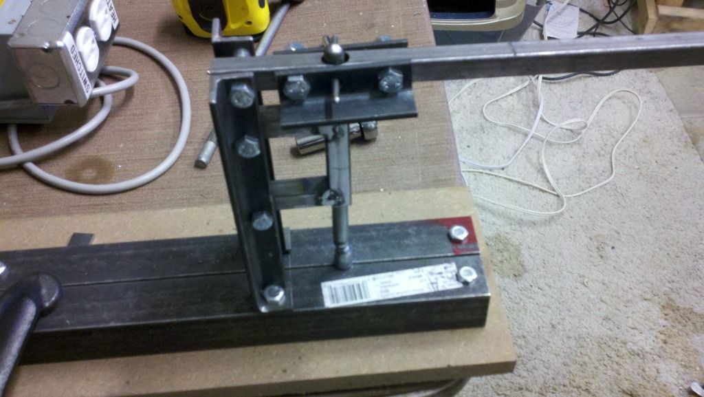
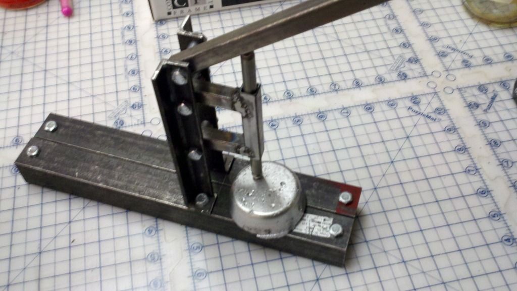
    So I spent the day manufacturing a Brinell Hardness Tester of my own design. Here's a photo of the finished product.


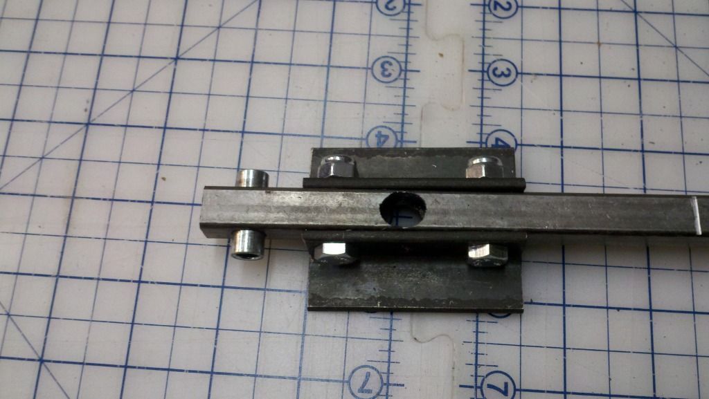
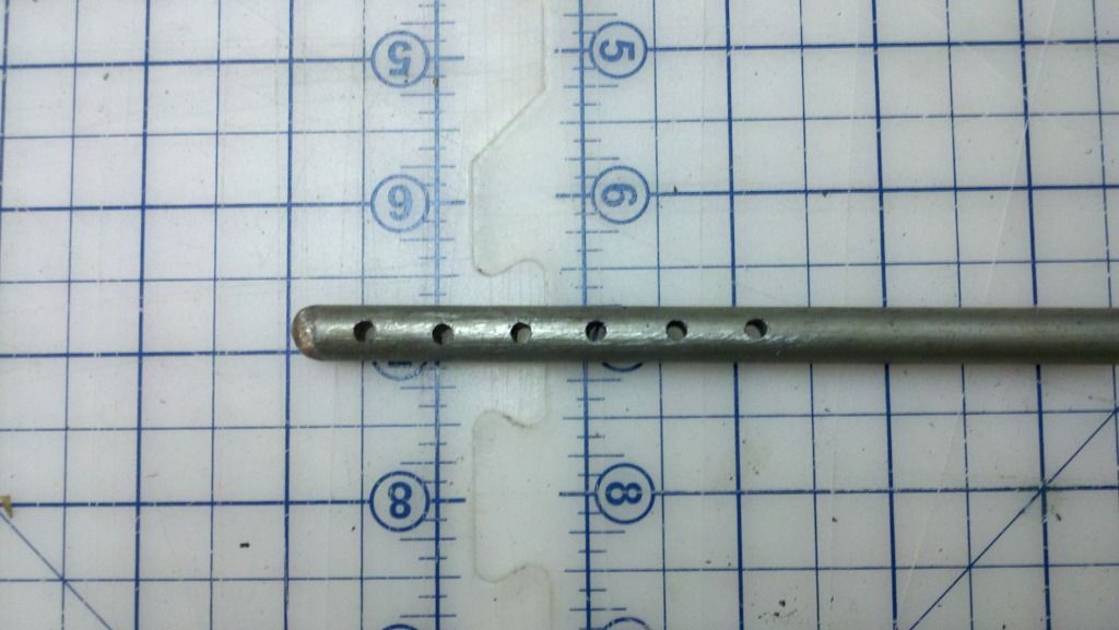
    The top lever presses on the indenter rod which in turn presses on a .375 inch ball bearing. The lever rod is about 32 inches long with notches cut every 5 inches. Based on the fulcrum distances I can calculate the leverage that multiplies the fixed weight hung from one of the notches. The indentor rod is a fixed 1.75 inches from the fulcrum.

    Using this formula: <Indentor force> = (<weight in lbs> * <inches from fulcrum>) / 1.75 inches. If I hang a 20lb weight at 20 inches from the fulcrum the force on the indenter is 228.5 lbs.

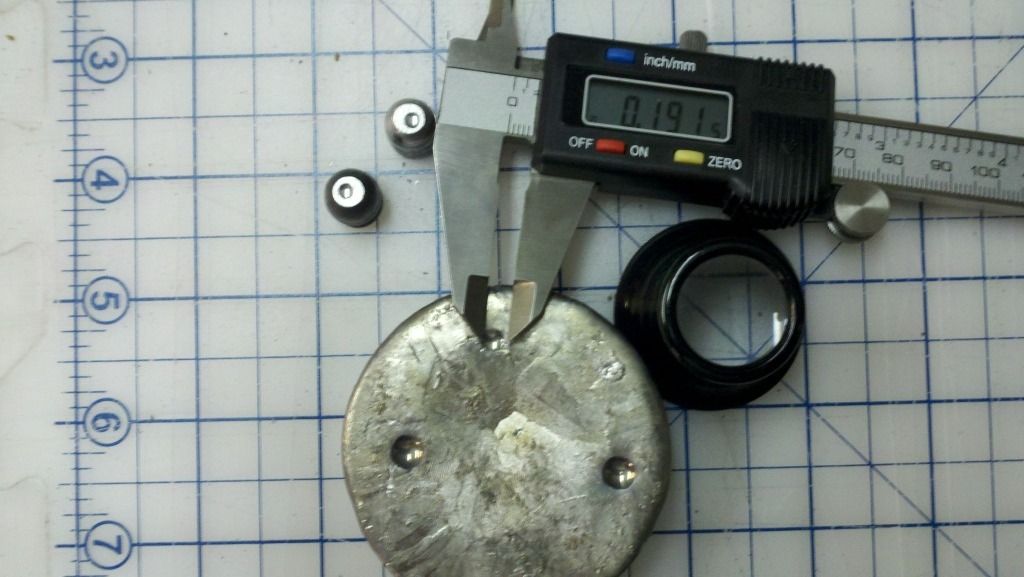
    Here are several test subjects and what I use to measure the indentation diameter. I use the loupe to get a more accurate caliper reading.


    The reading on the caliper is the diameter of the indentation of the shown ingot smelted from lead flashing material. When I plug in the numbers to the BHN formula using this calculator: a force of 228.5 lbs, indentor diameter of .375 inch and indentation of .1915 inch, I get a BHN of 5.18. I'd say that's purty darn close to what I'd expect of lead flashing, which is supposedly pure lead!

    Given that my control test is close to an expected 5, I tested two other cast boolits. One is a moly coated Bear Creek Bullets casting. It was a bad casting that I wasn't going to load anyway. I also tested one of the bad castings from my casting session yesterday. The results are:

    Bear Creek Bullets - 11.54 - indention diameter of .131
    My Boolit - 11.63 - indention diameter of .1305

    Holy cow! My castings are almost exactly the same hardness (harder in fact) than the purchased cast boolits!

    For giggles and grins I took a scrap of the steel I used to build the tester and tested it. I was surprised that I was able to easily see the indentation in the steel. Of course this isn't very hard steel and is made for easy weldability.

    Project Steel - 94.23 - indentation diameter of .0465

    I did take pictures of whole build, so if anyone is interested I can make a how-to posting. There are a lot of photos so it will likely take 2-3 posts to get all the steps. FIY, there is some welding involved for the indentor guide tube.
    Last edited by kylix.rd; 10-21-2012 at 11:22 PM.

  2. #2
    Boolit Buddy
    Join Date
    Mar 2012
    Location
    Southeast Missouri
    Posts
    252
    I would be very interested in some pics or build plans. I've been toying with the idea of buiding one myself....

  3. #3
    Boolit Bub tbj555's Avatar
    Join Date
    May 2012
    Location
    Illinois
    Posts
    61
    Yes I would also like build plans ,Looks like you did your homework...

  4. #4
    Boolit Master
    Join Date
    Feb 2007
    Location
    Communism running rampant!
    Posts
    4,756
    Very Good job!

    You may want to think about the static force of your apparatus before you hang the 20# out there. Ie. the weight of the handle and plunger.

    As I recall you might also want your lever as level as you can get it when you are indenting your test pieces.

    I wadded around on the net and found these optical goodies:

    http://www.electro-optix.com/opticaltools.html

    Best regards

    Three 44s
    Last edited by Three44s; 10-22-2012 at 02:25 PM.

  5. #5
    Boolit Bub
    Join Date
    Oct 2012
    Location
    California
    Posts
    35
    Quote Originally Posted by Three44s View Post
    Good job!

    You may want to think about the static force of you apparatus before you hang the 20# out there. Ie. the weight of the handle and plunger.

    As I recall you might also want your lever as level as you can get it when you are indenting your test pieces.
    Those are both considerations I'd made and will likely be tweaks to the design and calculations. My best guess for the static force is probably around 5-10lbs. That would probably only change the calculations by very small amount. As for the lever being level, I could probably compensate for that by calculating the actual vertical force vector based on the angle of the lever.

    Another solution would be to make the indentor pass through the lever with a locking screw. Then I can adjust the height of the indentor rod without changing the angle. However I'd have to strengthen the lever at that point. A couple of angle steel peices on either side of the hole should be sufficient. Hmmm... I know what I'm doing tonight .
    Last edited by kylix.rd; 10-22-2012 at 02:34 PM.

  6. #6
    Boolit Master
    bumpo628's Avatar
    Join Date
    Jan 2011
    Location
    SoCal
    Posts
    1,256
    Pretty slick.

    The difficult part is knowing the actual load. As mentioned above, the angle of the arm is going to change the load at the test piece. The height of the test piece will change the angle of the arm. Ideally, you could measure the load with some sort of scale that was the same height of the test piece so you won't have to calculate anything.
    Ronald Reagan once said that the most terrifying words in the English language are: "I'm from the government and I'm here to help".
    Download my alloy calculator here: http://castboolits.gunloads.com/showthread.php?t=105952

  7. #7
    Boolit Bub
    Join Date
    Oct 2012
    Location
    California
    Posts
    35
    Quote Originally Posted by bumpo628 View Post
    As mentioned above, the angle of the arm is going to change the load at the test piece.
    I think I have a solution to that problem as described in my previous post. I'll drill a hole into the lever bar through which the indentor rod will be fed. I'll reinforce the area with a couple of steel angle peices. I'll drill & tap a hole on the side for a thumb wheel screw that will lock the indentor into place and allow the lever to remain as close to level as possible.

    If there is a problem with the locked indentor keeping the lever from rotating enough at the lock point, I could drill holes through the indentor rod at .5" intervals and use a locking pin instead of a clamping screw.

  8. #8
    Boolit Buddy
    Join Date
    May 2011
    Location
    Colorado Springs, Co
    Posts
    303
    Could you place a scale under your lead piece and just read the load (down force) on the scale and calculate with that weight?

    Roger
    Let's make AMERICA Great again!!!

  9. #9
    Boolit Master
    Join Date
    Apr 2009
    Location
    New York
    Posts
    1,385

  10. #10
    Boolit Buddy
    Join Date
    May 2011
    Location
    Colorado Springs, Co
    Posts
    303
    Quote Originally Posted by zomby woof View Post
    Can you explain how the digital is tied into the arbor press?
    Thanks
    Roger
    Let's make AMERICA Great again!!!

  11. #11
    Boolit Buddy Gelandangan's Avatar
    Join Date
    Aug 2009
    Location
    Great Island Of Oz DownUnder
    Posts
    365
    I believe thats a digital clock to tell you how long the time for the test has elapsed.

  12. #12
    Boolit Master
    Join Date
    Feb 2007
    Location
    Communism running rampant!
    Posts
    4,756
    Quote Originally Posted by bumpo628 View Post
    Pretty slick.

    The difficult part is knowing the actual load. As mentioned above, the angle of the arm is going to change the load at the test piece. The height of the test piece will change the angle of the arm. Ideally, you could measure the load with some sort of scale that was the same height of the test piece so you won't have to calculate anything.

    Short of actually weighing the unloaded apparatus (in place) you could weight the arm and the rod separately and then calculate the moment arm effect and add that to whatever weight you add on the end of your beam.

    My wife built a cheese press from a design that's the same as your alloy hardness tester. She was able to reasonably level her beam by making the anchor point height adjustable to compensate for differences in cheese mold height.

    Cheese changes height while you are pressing.

    Best regards

    Three 44s

  13. #13
    Boolit Master

    Join Date
    Aug 2012
    Location
    North Carolina, USA
    Posts
    1,640
    Well, I guess it's time to get going on that redneck welder I've been wanting to build. I was hesitating because I really don't have a place to store two extra car batteries, never mind the modified hand truck I'll need to move them easily -- but this BHN tester means I now *need* to weld something...

  14. #14
    Boolit Bub
    Join Date
    Oct 2012
    Location
    California
    Posts
    35
    Thank you folks for all the awesome feedback and suggestions! I've completed the modification I described in one of my previous posts to this thread. I thought I'd present the results. As I had suspected, using a screw to clamp the indentor rod didn't allow it to pivot enough for the lever to press it down. So I modified the indentor rod by drilling small holes every .5" Then cross drilled the lever where the indentor passes through it. By placing a pin through that hole, it can pivot enough to press down on the indentor rod.

    Here's the modification to the lever and indentor.


    Here is the business end of things. As you can see, the lever is nearly level. This will minimize the error caused by reducing the vertical force vector from the angle of the lever. Using the pin and holes in the indentor, I can adjust for varying sizes of test material to get the lever as level as possible.


    Within the next day or so I'll post a followup thread that describes the project in more detail with lots of photos.

  15. #15
    Boolit Master
    Join Date
    Apr 2009
    Location
    New York
    Posts
    1,385
    Quote Originally Posted by Roger Ronas View Post
    Can you explain how the digital is tied into the arbor press?
    Thanks
    Roger
    With a magnet

  16. #16
    Boolit Master Gremlin460's Avatar
    Join Date
    Aug 2013
    Location
    Brisbane Au
    Posts
    864
    I am about to build something simular to this, will post pic's of the finished unit if there is still interest.
    Don't worry about life, no-one gets out alive.

  17. #17
    Boolit Master
    Join Date
    Jul 2014
    Location
    Arizona
    Posts
    4,679
    Nice work, and a lot of thought and engineering went into your design.
    How long did it take to actually make it once you worked out all the math ?

  18. #18
    Boolit Buddy
    Join Date
    Apr 2012
    Location
    Victoria, Au
    Posts
    337
    I know this is an old thread, I wonder how it will be to use ,say, an 8mm ball bearing with a FAT wrench, with the torque set on 60lbs , indent , then use the Brinnel calculator in the link above?
    TIA
    Please understand, I am technically challenged , but the idea translated it self and I appreciate feedback...
    "...Some days its rocket science, and some days it just zinc..."

Posting Permissions

  • You may not post new threads
  • You may not post replies
  • You may not post attachments
  • You may not edit your posts
  •  
Abbreviations used in Reloading

BP Bronze Point IMR Improved Military Rifle PTD Pointed
BR Bench Rest M Magnum RN Round Nose
BT Boat Tail PL Power-Lokt SP Soft Point
C Compressed Charge PR Primer SPCL Soft Point "Core-Lokt"
HP Hollow Point PSPCL Pointed Soft Point "Core Lokt" C.O.L. Cartridge Overall Length
PSP Pointed Soft Point Spz Spitzer Point SBT Spitzer Boat Tail
LRN Lead Round Nose LWC Lead Wad Cutter LSWC Lead Semi Wad Cutter
GC Gas Check