Inline FabricationTitan ReloadingReloading EverythingRepackbox
WidenersLee PrecisionMidSouth Shooters SupplyRotoMetals2
Load Data Snyders Jerky
Page 7 of 39 FirstFirst 1234567891011121314151617 ... LastLast
Results 121 to 140 of 768

Thread: Project - PID on Lee Pro 4 20 furnace

  1. #121
    Boolit Master


    snuffy's Avatar
    Join Date
    Feb 2007
    Location
    Oshkosh Wi.
    Posts
    1,747
    Thanks to Frozone for the link to the liquid-proof TC.
    http://cgi.ebay.com/1pc-K-Thermocoup...item1e5f529218
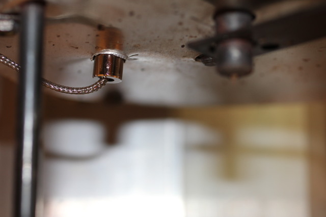
    I got one, then moved the location off to the side of where it was. It is now out of the way of molds being slid under the bottom pour spout. AND it does NOT leak. Also, I checked it against a brand new RCBS thermometer, the PID readout is only about 15 degrees lower than the temp on the dial. Just add that to the desired heat, no problemo.

    He is your friend, your partner, your defender, your dog.
    You are his life, his love, his leader. He will be yours, faithful and true, to the last beat of his heart.
    You owe it to him to be worthy of such devotion."

    “At the worst, if he fails, at least fails while daring greatly, so that his place shall never be with those cold and timid souls who know neither victory nor defeat”--Theodore Roosevelt

  2. #122
    Boolit Buddy Cranium's Avatar
    Join Date
    Mar 2011
    Location
    Central Florida
    Posts
    158
    Nice work!

  3. #123
    Boolit Bub kitsap's Avatar
    Join Date
    Nov 2010
    Location
    Western Washington State
    Posts
    59
    Quote Originally Posted by snuffy View Post
    Also, I checked it against a brand new RCBS thermometer, the PID readout is only about 15 degrees lower than the temp on the dial. Just add that to the desired heat, no problemo.
    Snuffy,

    Why don't you just adjust the offset in the PID controller and then the melt temperature will match the heat temperature set point??

    DougF
    Last edited by kitsap; 08-08-2011 at 10:46 PM.

  4. #124
    Boolit Master
    Mal Paso's Avatar
    Join Date
    Jun 2010
    Location
    Carmel, Ca
    Posts
    4,121
    I had a 40 degree discrepancy between 2 K type probes installed on 2 Lee pots and found this on the Auber Site:

    "For liquid and air measurement in a container, the length of the probe is also important factor if the sensor is mounted on the wall of the container. Normally, the temperature by the wall is lower than in the center. If the sensor is very short, the mounting on wall will function as a heat sink, it will drain more heater than the probe tip can pick up, making the reading constant lower."

    I removed the first probe from the bottom of the pot and remounted it like the photo with most the shaft inside and Now The Readings Match. Mounting On the bottom will work but the readings will be lower than actual. That little $6.85 thermocouple with the 1/4 - 20 Bushing removed works very well with 3/4" of shaft inside the pot. 45* angle to keep the height down, #21 drill is .003" over the probe shaft.

    Notes: That little TC-K6 probe is very rugged surviving installation, unsoldering and removal, and reinstallation. Auber has a FAQ but it isn't easy to find: http://www.auberins.com/index.php?main_page=page&id=6

    Pot's up to temp......Gotta Go
    Attached Thumbnails Attached Thumbnails PID4.jpg  
    Last edited by Mal Paso; 08-11-2011 at 11:05 AM.
    Mal

    Mal Paso means Bad Pass, just so you know.

  5. #125
    Banned

    Join Date
    Jul 2009
    Location
    The Great Land
    Posts
    998
    For those of you who may want a few 'bells and whistles'.

    If you used Auber # SYL 2342 or SYL 2352 as the PID.
    Here is a little circuit that will let you set up a visual alarm system.
    It uses the "deviation" alarms available on those 2 models.

    D1 through D6 are 1N4148s or similar. they should be ~5 cents each.
    R1 is a 1/4 watt carbon resistor, it should be safe to go as low as 330 Ω for Brighter operation. It depends on LED forward current - 330 Ω is ~ 35 mA current.
    The LED can be almost anything. I recommend either T-1 or T-1 3/4 size as they are the cheapest ~ 15 cents apiece.
    The relays are the PID alarm outputs.

    You DO need a DC power supply however.
    You can use something other than 12V.
    But if you use 6V reduce the value of R1 by 1/2 (160 Ω min) it's value. If 3V than 1/4 (80 Ω min).
    If you use 6V remove D3, D4.
    If 3V remove D2, D3, D4; and you'll need LEDs that have a forward voltage of less than 1.5V
    Attached Thumbnails Attached Thumbnails LEDsSCH.jpg  
    Last edited by Frozone; 08-14-2011 at 10:00 PM. Reason: added info

  6. #126
    Boolit Man
    Join Date
    Apr 2011
    Location
    Alaska and parts North
    Posts
    96

    My name is Kevin and I am electronically challenged

    To those of you who have posted your designs here to help the electronically challenged of the world (ME) successfully install a PID on my Lee Pro 4-20 all I can say is:

    THANK YOU!!!

    When I first started casting I did not understand how important pot temperature was and I made OK boolits but I wanted them to be like the ones Swede Nelson posts when the molds are done and I could not get mine to look like that. Worse yet, I could get them looking good once in a while but not always!!! That HURT.

    Then I bought a very nice mechanical thermometer for the pot and could see the temperature of the lead but do little to control it except turn that stupid rheostat knob about 20 minutes too late or a half hour too early.

    And then I stumbled in here and found this discussion going on.

    Interesting but I could never do anything like this..........so I bookmarked this thread.......re-read a day later........re-read a week later......etc.......or could I?

    Then a $100 dollar gamble that I would have a box of mysterious electronic junk left over and........

    It works and it "learned" and now my pot stays where I put it when I want it to - just like my dog!

    *doing that little mysterious electronic jig thing and jumping around*


    Thank you all! I understand everything except some "situation-thingee" that lead to the *B* word for somebody. My heart felt Thank You to all of you who helped me but never uttered a word!. I'm having a little PID party tonight in honor of that little electronic whoosis next to my pot and you are all invited over to help me "get the lead out" and hoist a couple.

    Sincerely,

    Kevin


    & PID's

  7. #127
    Boolit Master
    Join Date
    Mar 2011
    Posts
    1,320
    That really sums it up.........My casting improved 1000% when I built my PID. These little pots and casting for big boolits really causes huge fluctuations in temperature.

    I'm not sure how folks do without a PID........
    Roy B
    Massachusetts

    www.rvbprecision.com

  8. #128
    Boolit Buddy
    Join Date
    Jul 2011
    Location
    Toledo, OH
    Posts
    142
    Here's the one I built a couple weeks ago. Not quite done yet though, I still have to install the alarm lights. They're not really necessary, but they look cool!

  9. #129
    Boolit Mold hdugan's Avatar
    Join Date
    Apr 2009
    Posts
    5
    Quote Originally Posted by bigjason6 View Post
    Here's the one I built a couple weeks ago. Not quite done yet though, I still have to install the alarm lights. They're not really necessary, but they look cool!
    Looks good! One thing I noticed, What kind of wire did you use from the TC jack to the PID? It looks like standard hookup wire. You don't want to do that!

    You need to use TC wire for that connection. Make sure that the TC wire colors match from jack to plug. Just cut a little wire off the end of the TC you got in the kit.
    --

    Do Not Fold, Spindle, or Mutilate

  10. #130
    Boolit Buddy
    Join Date
    Jul 2011
    Location
    Toledo, OH
    Posts
    142
    Quote Originally Posted by hdugan View Post
    Looks good! One thing I noticed, What kind of wire did you use from the TC jack to the PID? It looks like standard hookup wire. You don't want to do that!

    You need to use TC wire for that connection. Make sure that the TC wire colors match from jack to plug. Just cut a little wire off the end of the TC you got in the kit.
    I'm just curious, but what difference does the wire make? Is it the resistance in the wire? Thanks!

  11. #131
    Boolit Mold hdugan's Avatar
    Join Date
    Apr 2009
    Posts
    5
    Quote Originally Posted by bigjason6 View Post
    I'm just curious, but what difference does the wire make? Is it the resistance in the wire? Thanks!
    See this from Auber. Specificly #2.

    It's not the resistance, as I understand it, it's the contact between the different metals.
    --

    Do Not Fold, Spindle, or Mutilate

  12. #132
    Boolit Buddy Cranium's Avatar
    Join Date
    Mar 2011
    Location
    Central Florida
    Posts
    158
    Quote Originally Posted by bigjason6 View Post
    Here's the one I built a couple weeks ago. Not quite done yet though, I still have to install the alarm lights. They're not really necessary, but they look cool!
    wow....very professional looking!

  13. #133
    Boolit Buddy
    Join Date
    Jul 2011
    Location
    Toledo, OH
    Posts
    142
    Quote Originally Posted by Cranium View Post
    wow....very professional looking!
    Well, thank you kind sir!

  14. #134
    Boolit Man
    Join Date
    Apr 2011
    Location
    Alaska and parts North
    Posts
    96

    Alarm excitation voltage?

    I'm almost embarassed to ask any questions here because I already feel like I copied off of all of your tests or something (I have this image of the people at Auberins scratching their heads and wondering why they keep getting the same order from all over the country). But I really am electronically challenged. I have other talents but I always figured that if people were supposed to understand electronics that we would have been born with multi-meters instead of hands?

    Anyway my question is this. I followed the wiring diagram for the alarm (all two wires) and I think that I purchased the correct alarm LED (FLBuz-120-16) for the 1/16 DIN Controller (SYL-2352). I think that the alarm output is 110V from terminals 1 and 13 of the controller and I bought a 110V input LED/buzzer alarm that does not require a separate (DC) power supply. Am I wrong in the understanding that the controller is sending out a 110V excitation signal to activate the alarm?

    I have programmed the controller to activate alarm1 (ALRM-1) in the case of an "over-temperature event" and the alarm event is lighted up on the front face of the controller but not the external buzzer/LED. All that I am attempting to do is provide a secondary notification if something goes south and the pot is going nuclear.

    I wired the whole thing up according to Figure 8 in the instructions for the 2352 controller with the exception that I wired a duplex outlet in place of the "heater" that they indicate in the wiring diagram and then I simply plug my Lee Pro 4-20 into one of the outlets and leave all of the Lee wiring as it came from the factory. This means that the warranty will still be in effect and I simply leave the pot rheostat set to "10" and let the controller keep the temperature constant by switching the voltage to the pot on and off. Which is why I want the "over-temperature event" alarm - for when I descend into the "Casting Zone" and forget to check that the pot is still functioning well. In that case, something fails and the pot voltage is simply left on continuously and I am blissfully and obliviously incinerated while laughing maniacally and holding up "THE" perfect Boolit!

    Can anybody troubleshoot this mess that I have come up with without being in my shop? You are welcome to come to the shop but it is likely to be a long drive for some of you?

    Thanks a priori for any help that you can give.

    Kevin

    Last edited by Mauser Rat; 08-22-2011 at 05:13 AM.

  15. #135
    Boolit Mold hdugan's Avatar
    Join Date
    Apr 2009
    Posts
    5
    Quote Originally Posted by Mauser Rat View Post
    Am I wrong in the understanding that the controller is sending out a 110V excitation signal to activate the alarm?


    Yes, you are incorrect. The relays are simple switches, unlike the SSR output , they output no voltage from the PID.

    On the SYL 2352, outputs #1, #13 and #14 are relay connections.
    #1 is a 'common' connection shared by both relays, #13 and #14 is the Other side of each relay. You need to run one leg of the 120V supply to pin 1 in order to get any voltage out of #13 or #14.


    One side of the 120V goes to pin #1. Pin #13 goes to one wire of your buzzer. The other side of the 120V goes to the other wire of the buzzer.
    Last edited by hdugan; 08-22-2011 at 06:01 AM.
    --

    Do Not Fold, Spindle, or Mutilate

  16. #136
    Boolit Man
    Join Date
    Apr 2011
    Location
    Alaska and parts North
    Posts
    96
    hdugan,

    Thank you sir or madam. I will make the changes that you describe. I do not know what arcane form of mysticism allows one to fathom such knowledge independently. Is there some mystical writing that one such as I could lie prone in front of for a period of time and gather such knowledge directly? In other words how in the world do you guys all know all this stuff? I THOUGHT that I had read the directions pretty carefully but I must have been sick that day!

    My sincere thanks again,

    Kevin

  17. #137
    Boolit Man
    Join Date
    Apr 2011
    Location
    Alaska and parts North
    Posts
    96
    hdugan,

    Thanks again. I wired it as you indicated and purposely caused an alrm1 situation and the sound was devastating. Took me a few seconds to figure out how to turn it off with all of that noise!

    I owe you one although I still have no idea how you all know how these things are activated? I read the instructions again and I find nothing about getting power to terminal 1 and completing the circuit back to neutral. Since I had already supplied the thing with line and neutral I figured the output signal simply needed to go through the relay?

    Thanks,

    Kevin


  18. #138
    Boolit Man
    Join Date
    Apr 2011
    Location
    Alaska and parts North
    Posts
    96

    Another stupid question...

    There is a discussion going on in the "Casting" forum about which setting on the Lee 4-20 pot corresponds to what temperature etc. I know from here that the rheostat is almost hopelessly incapable of controlling the heat the way that it should be controlled to cast uniform and predictable boolits but there is no way that I was going to jump in and start talking about things that I am only barely mastering now .

    BUT

    Then someone over there, that used a PID in which the "relay" burned out, said that the PID should NOT be used while the pot is coming up to temperature because the SSR does not like the level of switching that is going on then? That sounds more like a mechanical relay to me - not an SSR?

    One of them suggested plugging the pot into outlet power until it is "up to temperature" and then plug it into the PID to control the already established temperature to avoid burning out the SSR. In watching my PID it seems like it cycles more in trying to hold the pot once it has reached temperature than during the initial ramp up.

    Question to you smart guys and/or gals: Is it true that the PID should NOT be used during the initial ramp up to 650 or so degrees F? Should the pot be plugged into a regular outlet during temperature ramp up?

    Thanks in advance and the other discussion is in the "Casting" forum.
    Last edited by Mauser Rat; 08-24-2011 at 11:24 AM.
    Have a good day,

    Kevin


  19. #139
    Boolit Buddy
    Join Date
    May 2011
    Location
    Colorado Springs, Co
    Posts
    303
    I saw that also and question it. I never read it anywhere else like that poster stated that it was posted. I would guess that using a PID is like a Ronson Showtime cooker. "SET IT AND FORGET IT".

  20. #140
    Boolit Master
    Join Date
    Mar 2011
    Posts
    1,320
    I've been using my PID on two different pots from start-up to 650-700 degrees with zero issues. The PID is a simple temperature copntrolled switch. As long as the "relay" can handle the current I can't see where there would be any issues.
    Roy B
    Massachusetts

    www.rvbprecision.com

Page 7 of 39 FirstFirst 1234567891011121314151617 ... LastLast

Posting Permissions

  • You may not post new threads
  • You may not post replies
  • You may not post attachments
  • You may not edit your posts
  •  
Abbreviations used in Reloading

BP Bronze Point IMR Improved Military Rifle PTD Pointed
BR Bench Rest M Magnum RN Round Nose
BT Boat Tail PL Power-Lokt SP Soft Point
C Compressed Charge PR Primer SPCL Soft Point "Core-Lokt"
HP Hollow Point PSPCL Pointed Soft Point "Core Lokt" C.O.L. Cartridge Overall Length
PSP Pointed Soft Point Spz Spitzer Point SBT Spitzer Boat Tail
LRN Lead Round Nose LWC Lead Wad Cutter LSWC Lead Semi Wad Cutter
GC Gas Check