Good to know. They don't work very well the way they are now.Originally Posted by Frozone

I didn't really know how they were supposed to go on. I'll change them.

|
   
   
|


|


Good to know. They don't work very well the way they are now.
After reading this thread a couple of times, I ordered all the stuff today to build my PID... I'm sure I will have to refer back to this sticky, but I'm looking forward to the build and ultimately using it!
Also, this is my first post!
Thanks


You fellows are costing me MONEY. Long as I've got the stuff coming to build mine how about another dumb question? I've been through the stickies 4 times now clipping out notes and should have most of it figured out (I think) as far as wiring. Long as I'm in it this far was thinking I'd put a couple lights in on the high and low temp alarms. (Might as well use that cabinet front for something!)
Would these be suitable for that? Was thinking 215803, 205812, and 205830.
http://www.jameco.com/webapp/wcs/sto...type=jamecoall
Mike
Benefactor Member NRA
Life Member Iowa Firearms Coalition
US Army Vet
There are two ways to conquer and enslave a nation.
One is by the sword. The other is by debt.�
John Adams 1826
You mean 215812 and 215830.
All 3 are neon so it looks like you'll use the input AC and run it through alarm relays for the lights. I did one like that.
Does your controller have 2 alarms? Both with relay outputs, not SSR outputs?
I added the missing components in my Mypin to get the second alarm output. Alarm 1 (relay) turns on a green neon light when the pot is within 15deg (or whatever I set it for) of my setpoint and alarm 2 (SSR output, 24V) turns on a red LED light if the pot goes 20deg over setpoint.
Radio Shack has neon and LED panel mount lamps.
"The urge to save humanity is almost always a false front for the urge to rule." --H. L. Menchen
Mine is a SYL-2352 so as I understand it 13 & 14 will put a signal out. Not voltage but triggers the SSR and wired properly will light for a low temp or high temp alarm. Figured I'd also wire one into a switch that would turn the whole unit on while I was at it. Mainly just wondered if the neon's were OK rather than a LED. These would be getting 120V when fired up. Am getting a 25a SSR BTW.
Mike
Benefactor Member NRA
Life Member Iowa Firearms Coalition
US Army Vet
There are two ways to conquer and enslave a nation.
One is by the sword. The other is by debt.�
John Adams 1826
I don't think 13 and 14 put out any signal, they are just switch contacts. Pg 2 para 3.4.2 describes that.
There's a world of difference between-
- neon bulbs (110V, very low current)
- LEDs (low voltage DC several mA current)
- and incandescent lights (low voltage AC or DC).
and between PID controller outputs-
- "SSR output" implies 12-24VDC coming out of the controller, maybe 20mA current or so, to turn on an SSR but can also turn on a low voltage light,
- "relay output" is only a set of on-off contacts inside a relay. It can switch something on or off but doesn't supply electricity.
You can use a relay output to control a neon bulb by hooking the black (hot) wire of the 110VAC to one lead of the neon bulb, the other neon bulb lead to one relay contact, and the other relay contact to the white 110VAC line.
If one of the alarm outputs is designed to control an SSR you can't use a neon bulb, you'll be limited to a low voltage LED or incandescent. Pay attention to the current requirements of either, the PID output is good for up to around 20 mA, or whatever the manual specifies.
The manual indicates the main output is the "SSR" type (good) but the alarms are relays. And it looks like your controller has one terminal going to each of the two relays, so that's the one you'd stick one side of the AC into (recomment the white neutral wire).
http://auberins.com/images/Manual/Ma...sion%203.4.pdf
"The urge to save humanity is almost always a false front for the urge to rule." --H. L. Menchen
Could someone who has completed a PID recently share what parts you used and where they can be found? I would like to make a unit with a 110 outlet to plug the pot into. Electrical novice here.
I'm not a promoter but I'd strongly suggest starting with seeing Frozone's offering, he has a completed plug'n'play unit or the same thing in kit form. Otherwise you'll be learning the basics of what goes into it and then shopping for the stuff. There are several examples of PID construction projects here, all of them different but using the same functional pieces.
http://castboolits.gunloads.com/foru...hp?116-Frozone
"The urge to save humanity is almost always a false front for the urge to rule." --H. L. Menchen
Yeah I am aware of what frozone has to offer, I would like to build something similar. I am good with my hands I am sure I will not have a problem figuring it out and will save myself an extra 100 dollars.
I just need a simple list of parts that will output what I am looking for.

If I was in the US, I'd go with what Frozone offers. You won't save $100 by cobbling one together yourself with dodgy chinese made cr@p.
But if you insist on making it hard for yourself (like I did!) basics are a PID, a thermocouple and an SSR. These can be had as a complete set off eBay for about $25, BUT:
Is the thermocouple capable of higher temps for melting lead?
Is the PID capable of higher temps for melting lead?
Is the SSR of a good enough quality to do the job?
I ended up spending hours and hours researching what I should get, then spent way too much time cutting a square hole in an old PC power supply box, cutting wires, soldering terminals, etc, etc. And after all that, the PID was a relay output type, not an SSR output, so I had to dig into the PID to remove the relay and jumper the terminals to get an SSR output.
So, sure, I finally got one which works, but it really was a lot of hassle.
And while I am no electrical/electronic expert, I know enough to be dangerous
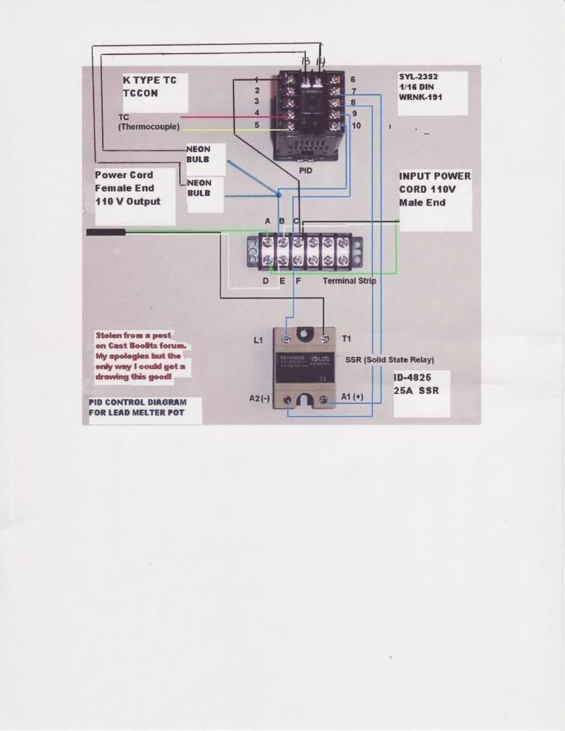
It's my under standing you wire 110 to the #1 on PID. When #13 see an alarm (or #14) it completes with #1. Other side of Neon would then go to the neutral common on the Terminal strip to complete the circuit. I butchered a schematic on this forum and drew in the jumpers. Please correct me if I don't have this figured out properly
Mike
Benefactor Member NRA
Life Member Iowa Firearms Coalition
US Army Vet
There are two ways to conquer and enslave a nation.
One is by the sword. The other is by debt.�
John Adams 1826
I think all you need to do is swap what's going to 1 and 13. In the manual, 13 is the common to both relays. Terminal 1 is alarm1, terminal 14 is alarm2.
I'm looking at pg1 section 3.
On another note, I'd suggest putting the AC neutral (white wire) to the relay common, terminal 13, and hook the neons directly to AC hot (black wire). The reason is to keep unlimited 110V off of the controller relay terminals. If the hot 110V only goes directly to the neons then a short circuit anywhere on the other side of the neons won't melt anything. It'll work either way though.
Last edited by el34; 01-09-2014 at 08:26 PM.
"The urge to save humanity is almost always a false front for the urge to rule." --H. L. Menchen
I had to do the same thing, not knowing what RNR and SNR meant when I ordered the PID. But then I used the extricated relay to populate alarm 2 (plus a few other parts) to get an SRR so I could hook up something to alarm2.
"The urge to save humanity is almost always a false front for the urge to rule." --H. L. Menchen
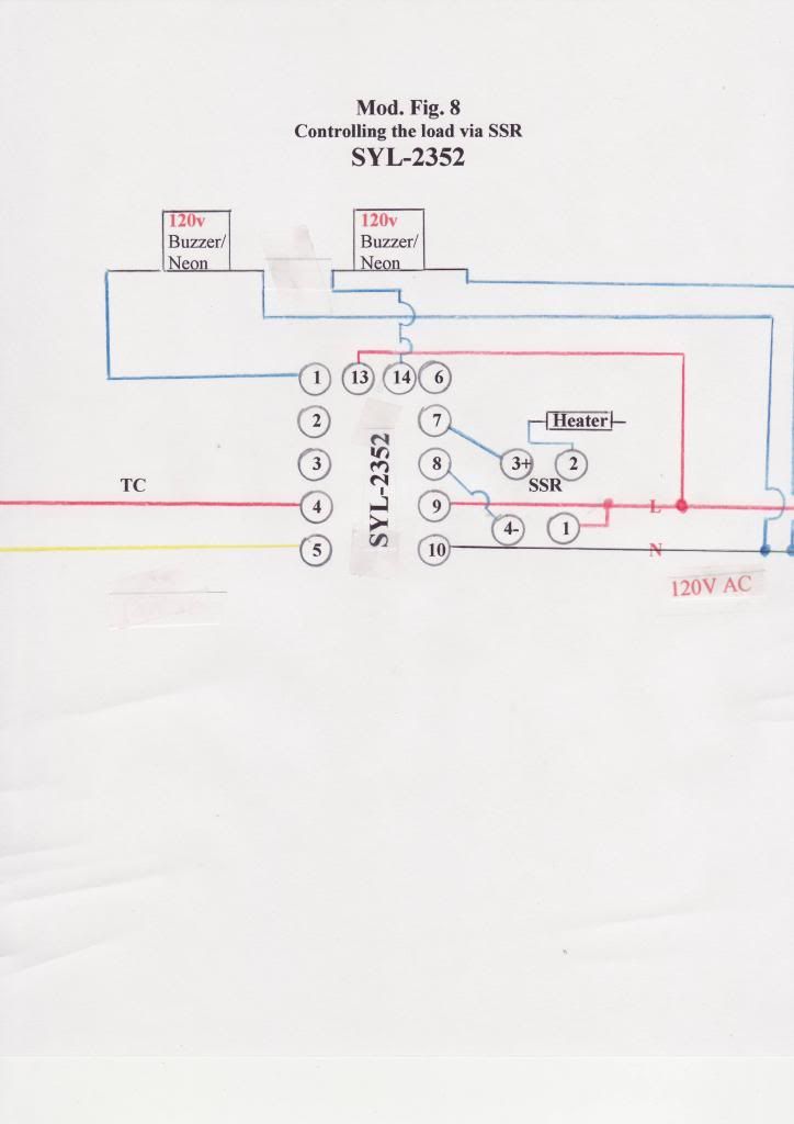
Since looking thru the Auber manual pretty carefully I came up with a modification of Fig. 8 showing 2 alarms used. 13 appears to be common to 1 & 14 so 13 gets the Line connected to it. Alm 1 makes contacts 1 & 13 completing the circuit to Neutral. Alm 2 would be 13 & 14 mating and returning to neutral. Danged if I know what "RTD" so I just showed the TC where it's supposed to connect. Think I'll run this by Auber's techs to be sure though.
Mike
Benefactor Member NRA
Life Member Iowa Firearms Coalition
US Army Vet
There are two ways to conquer and enslave a nation.
One is by the sword. The other is by debt.�
John Adams 1826
You've got it now. If you didn't see it I'd suggest checking my earlier post to you regarding keeping the full power AC line (black wire) off of the relay contacts and using the relays to switch neutral but it's just a safety precaution that probably won't ever be important.
An RTD is a Resistive Temperature Detector, which is just a resistor whose resistance changes with temperature. It is another type of sensor that the controller can use but we don't care, a thermocouple works better for our purposes. Be sure to notice a TC has a + and - and hook it up like your drawing.
Last edited by el34; 01-09-2014 at 11:05 PM.
"The urge to save humanity is almost always a false front for the urge to rule." --H. L. Menchen
Got to quit looking at this stuff tonight, getting x-eyed! Will look those posts over tomorrow and let them soak in. So what's a "SNR" and a "RNR"? Appreciate all your help. Think the road conditions have screwed up my parts delivery but maybe get em' if FedEx works on Sat.
Mike
Benefactor Member NRA
Life Member Iowa Firearms Coalition
US Army Vet
There are two ways to conquer and enslave a nation.
One is by the sword. The other is by debt.�
John Adams 1826
Mypin is a popular brand of PID controller. They're made in China but from all I've seen they work well and reliably. I am using one, and Frozone's offerings use Mypin.
They use the three-letter designations to identify the electrical nature of the outputs. "S" means an output that produces 24VDC to fire a solid state relay, "R" means the outpt is just a set of relay contacts, and "N" means no output at all.
The positioning is in the order: main output - alarm2 output - alarm 1 output.
So SNR means-
S - main control output is for connecting to a solid state relay,
N - alarm2 isn't in there,
R - alarm1 is relay contacts.
An easy mistake is to go on ebay and unknowingly order an RNR version. Its output won't work with a solid state relay (SSR) without intervention.
"The urge to save humanity is almost always a false front for the urge to rule." --H. L. Menchen

Mookiie, I agree with Norbrat - for those in the US Frozone's offering is very good value, and pretty well guaranteed to work. Yes, you can save yourself some money by doing it yourself, although that depends on just how much you have to buy. If all you need are the PID, SSR and K-probe, and you have everything else you need, then by judicious shopping you can probably pick up the three items for maybe $35. BUT it will not be a Mypin PID, they are nearly twice the price of other brands. AND that also assumes that you buy the right kind of PID - you have to read the specs carefully to figure out which ones have SSR outputs. You also have to work out how to programme it (I suspect some of the "instruction" books leave a lot to be desired).
Also, if you are an electrical novice you need to be very careful working around mains voltage AC. If you make a mistake, and are lucky, you'll just cook the components. If you're unlucky you'll cook yourself!
As for a list, how's this for starters -
PID
SSR
K-probe (at least 600 degrees C, preferably 800C, at least 8" probe length)
Suitable case to put it all in
Suitable wire, connectors (crimp and/or solder type) and heat shrink to cover them
Mains (AC) input and output plugs/sockets
Heat sink and thermal paste for the SSR
On/off switch
Possibly LEDs if you want to connect the alarm outputs (depending on the PID)
A suitable terminal strip for commoning the mains feeds
Assorted nuts and bolts for fitting things together.
That's all I can think of off the top of my head. Just let me emphasize again - be very careful working around mains AC. It is very unforgiving if you make a mistake, and even experienced electricians get jolts from time to time, so please be careful.
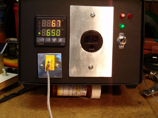
Got it done, works like a charm - better than my cheap camera skills for sure! Found out my Tel Tru reads a good 50 degrees low and think I can calibrate that with the nut on back of it.
Was wondering about setting the Input Offset (Pb). Ice water reads 2 Celsius and 208 F. From that what would I input for a figure or is that an experimental operation?
Mike
Benefactor Member NRA
Life Member Iowa Firearms Coalition
US Army Vet
There are two ways to conquer and enslave a nation.
One is by the sword. The other is by debt.�
John Adams 1826


I wouldn't worry about a few degrees of error.
The unit itself is only accurate to about 3�C over it's full scale with a K type TC.
Plus the K type itself is not the most accurate thermocouple made.
Add to that we use it in it's gray area - around 354 �C ( it's cure point) the K is not linear.
It also has up to 5� of drift over time.
Anything less than 7� of error is a pretty good thing.
 Posting Permissions


| BP | Bronze Point | IMR | Improved Military Rifle | PTD | Pointed |
| BR | Bench Rest | M | Magnum | RN | Round Nose |
| BT | Boat Tail | PL | Power-Lokt | SP | Soft Point |
| C | Compressed Charge | PR | Primer | SPCL | Soft Point "Core-Lokt" |
| HP | Hollow Point | PSPCL | Pointed Soft Point "Core Lokt" | C.O.L. | Cartridge Overall Length |
| PSP | Pointed Soft Point | Spz | Spitzer Point | SBT | Spitzer Boat Tail |
| LRN | Lead Round Nose | LWC | Lead Wad Cutter | LSWC | Lead Semi Wad Cutter |
| GC | Gas Check |

 Reply With Quote